Download
1 / 23
230 likes | 354 Views
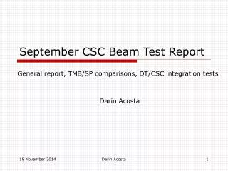
September CSC Beam Test Report. General report, TMB/SP comparisons, DT/CSC integration tests Darin Acosta. Where to find information. Documentation: http://www.phys.ufl.edu/~acosta/cms/trigger.html Includes scanned pages from log books and links to online log and other web sites Data:

E N D
September CSC Beam Test Report General report, TMB/SP comparisons, DT/CSC integration tests Darin Acosta Darin Acosta
Where to find information • Documentation: • http://www.phys.ufl.edu/~acosta/cms/trigger.html • Includes scanned pages from log books and links to online log and other web sites • Data: • /castor/cern.ch/user/t/tbx5ccdr/ • “rfdir” for listing“rfcp” for copying (may need to wait a long time as data is staged from tape) • Runs 5018 5164 • Correlated SP data starts with run 5108 Darin Acosta
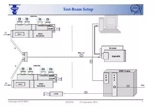
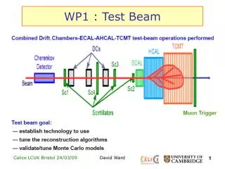
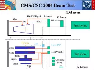
Beam Test of 2 CSC’s at X5a / Goal: complete electronic chain test of data transmission from CSC front-end electronics to the Track-Finder trigger, all operating synchronously with the 40 MHz structured beam MPC and SP included in tests, various clocking solutions tried Darin Acosta
CSC Peripheral Crate From front-end cards CCB + TTCRx MPC DDU 2 TMBs and DMBs (CSC id’s 3 and 8) Darin Acosta
CSC Track-Finder Crate CCB + TTCRx Sector Processor MPC for in-crate tests Darin Acosta
CSC Track-Finder Trigger Home-built VCXO & PLL clock patch added to clean incoming TTC clock for links, but TTC QPLL also tested Test 3 × 1.6 Gb/s optical link connections from CSC electronics Uses TLK2501 chipset Requires very stable reference clock for error-free operation Darin Acosta
Test Results • Using home-built VCXO+PLL solution for 80 MHz reference clock to TLK2501 receivers: • PLL locks to incoming machine clock(Once Bruce Taylor helped us set up the TTCmi crate correctly) • Measured frequency: 40.078893(1) MHz • No errors on optical links reported over many hours of PRBS and data tests • Continuous data transmission or framed mode (idle frames sent) • Data successfully logged by both CSC DAQ and CSC Track-Finder readout • SP data FIFO synchronized to L1A Darin Acosta
TTC QPLL Mezzanine card (TTCRq) • Three made available to CSC group for testing during Sept.03 structured beam test • Provides stable clock signalsat 40, 80, and 160 MHz at correct LHC frequency • Installed on CCB with 40 MHz clean clock sent to backplane, 80 MHz clock sent by twisted pair to SP or MPC • Noticed that CCB commands have 1 BX extra latency with TTCRq Darin Acosta
TTCRq (QPLL) Test Results • QPLL 80 MHz clock directly to MPC transmittersLev’s VCXO+PLL for SP receivers • No link errors for 20 minute PRBS test • QPLL 80 MHz clock directly to SP receiversMPC uses default clock multiplier • No link errors for 15 minute PRBS test • Successfully logged data for 10K events (run 5151) • QPLL 40 MHz clock on TF crate backplane SP uses DLL in FPGA for clock multiplier • Link errors observed in PRBS test • TTCRq on CCB in peripheral crateTTCRm on CCB in TF crate • Able to take data with same trigger efficiency (i.e. TTCRq works for peripheral crate as well) Darin Acosta
Data-taking Mode • Most data logged using two independent DAQ systems: • CFEB Control for DDU data run00nnnn.dat • SP DAQ for Track-Finder data SPDAQ*.dat • Maximum data rate limited to ~400 L1A/spill • Main DAQ PC not as optimized as OSU’s dual-CPU with SCSI disks • Maximum rate is coincidentally the same for both DAQs • XDAQ version by Wilkinson, Tumanov, et al. also apparently logs data correctly • Underlying SP code the same as for standalone DAQ since it was written using XDAQ • All analysis of SP and DDU data done using the “DataFormat” packages Darin Acosta
SP Data Format 5 BX read out per L1A (most data on BX2) L1A BXN frame1, frame2 of LCT1 on BX2 frame1, frame2 of LCT2 on BX2 frame1, frame2 of LCT1 on BX2 frame1, frame2 of LCT1 on BX3 ff05 f003 f000 f2e8 1 2 ff96 1 2 8163 2 2 ff0a 2 2 3038 2 ff05 f004 f000 f2d6 1 2 ff97 1 2 8168 1 3 f60b 1 3 343d Darin Acosta
Comparison of TF Data with DAQ CSC Data from DAQ CSC Track-Finder Data CSC 1 CSC 2 Darin Acosta
LCT BX Information from TMB • From TMB Header information, use BXN at Pretrigger and the LCT BXN offsets to compute BXN for each LCT • Run data through MPC simulation to compare with SP Darin Acosta
TMB – SP Data Comparison • SP BXN – TMB BXN @ Pre-trigger = 44 typically • Is this difference affected by CCB command delays? • Empirically find: • If LCT BX Difference = 0x1 Add +1 to TMB BXN • If LCT BX Difference = 0x2 Add +2 to TMB BXN • If LCT BX Difference = 0x3 Add -1 to TMB BXN • Comparison between SP and TMB for all 5 BX read out by SP for every L1A match: • Muon runs, 60K events: 98.3% agreement • Pion runs with TTCRq, 10K events: 97.6% agreement • Mismatches between TMB and SP data are in BX assignment only, not in LCT frames Darin Acosta
SP – TMB Mismatches Run5126, evt 25 (accel on) DDU Data: TMB BXN @ L1A: 786 TMB BXN @ Pretrigger: 667 LCT0 BXN Diff: 1 LCT1 BXN Diff: 1 TMB: f70a 3037 TMB: e70a 3037 TMB BXN @ L1A: 786 TMB BXN @ Pretrigger: 669 LCT0 BXN Diff: 1 LCT1 BXN Diff: 1 TMB: e617 803e TMB: 9617 803e SP Data: BX:713 BX1 M1: f70a 3037 BX1 M2: e617 803e BX1 M3: e70a 3037 Prediction is that LCTs from different TMBs differ by 2 BX But SP sees data on same BX (agrees with first TMB, not second) Note ghost segments: same strip/WG, different quality Darin Acosta
SP – TMB Mismatches, Cont’d • Nearly all of the mismatches involve differing BX assignment for LCTs from the TMB for csc#8 • Data frames are in agreement, however • Excluding csc#8 in these cases and comparing TMB and SP for csc#3 near perfect agreement • Just 32 discrepancies from an analysis of 60K events, where BX assignment of TMB for csc#3 differs • For these mismatches, the SP usually has the LCTs on the central BX in the SP read-out • So trigger data appears to be good! • Conclusion for DAQ readout of TMB data: • TMB #8 has BX error 2% of time • TMB #3 has BX error 5×10⁻⁴ of time • This increased to 5×10⁻³ for runs with TTCRq in Peripheral crate (which changed the timing) Could be 2 or more BX off from SP Darin Acosta
MPC Sorting Problem? • 2 mismatched events had LCTs in different order in SP readout vs emulation: • SP read out: • M1: a180 3140 (frame1 frame2 of muon1)M2: a200 3438 • M1: fd09 3038M2: fd0a 3038 • Emulation from Greg P. had the order swapped Darin Acosta
Other effects • TMB/SP mismatch rate seems independent of ALCT delay setting (timing scan runs) • When DDU errors occur in DAQ, lots of TMB/SP mismatches result • SP DAQ FIFO sometimes fills up if L1A rate is too high • Affected pion runs mostly • BX counter still increments, but data is frozen at last event • Need to add FULL flag to event header Darin Acosta
First DT/CSC Integration Tests DT TF transition card CSC TF transition card Darin Acosta
DT/CSC interface • Reminder: data is exchanged between the two systems for efficient coverage of the region 0.9 < || < 1.2 • CSC sends 3 LCT’s/BX (52 bits) from ME1 to two 30° DT sectors • DT sends 1 segment/BX (26 bits) from each 30° sector • Signaling standard is LVDS at 40 MHz through SCSI cables and connectors • Layout problem on CSC transition card meant connectors had to be attached on opposite side of board • Cable connector had to be flipped 180° at one end so that signals are received on correct pins • Only had time to make & test custom 1m cables • Signals inverted in firmware to handle polarity change Darin Acosta
DT CSC transmission test • DT Data Source Card DT TF DT transition card CSC transition card CSC TF • Data was received in a FIFO in the main FPGA of the SP mezzanine card • BC0 marker sent on first data word • Tested walking 1’s, walking 0’s, & simulated muon data • All bits and clock were received, but some bits were swapped at DT output before being sent to CSC Darin Acosta
CSC DT transmission test • CSC TF CSC transition card DT transition card DT TF • Data is sent from Front FPGAs, bypassing LUTs, and delivered to CSC transition card • Tested walking 1’s and walking 0’s • DT TF has no FIFO to store received data • Two dead TTLLVDS buffer chips on CSC transition card leads to 7 missing signals • But signals are OK and in correct order on SP backplane connector • Remaining signals are seen by DT TF, albeit with limited storage capability Darin Acosta
DT/CSC Conclusions • Initial tests show that DT and CSC Track-Finders can exchange data • First integration test between UF and Vienna (good check on documentation!) • A few minor problems on both ends with swapped bits, connectors, and dead chips • Tests should be repeated with longer cables representing situation in counting room • Modified cables arrived too late at CERN for testing • More sophisticated tests of synchronization procedure and Track-Finding with both CSC and DT data should be performed in future • DT Track-Finder currently has only limited means of data storage Darin Acosta