Download
1 / 50
510 likes | 638 Views
Learn about the anatomy of the cervical spine, common injuries, stability assessments, Denis' 3-column concept, mechanisms of injury, diagnostic principles, and initial management strategies.

E N D
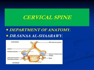
Anatomy • The spine contains 33 vertebrae: seven cervical, 12 thoracic, 5 lumbar, 5 fused sacral and 4 fused coccygeal vertebrae • The vertebral bodies generally increase in width craniocaudally (exception of T1–T3) • Normal spinal curves include cervical lordosis, thoracic kyphosis, lumbar lordosisand sacral kyphosis
Cancellous bone in cortical shell • Vertebral canal between body and lamina: houses the spinal cord • Vertebrae: • 1. Body (centrum): have articular cartilage on superior/inferior aspects; get larger inferiorly • 2. Arch (pedicles & lamina) • 3. Processes: spinous, transverse, costal, mamillary • 4. Foramina: vertebral, intervertebral, transverse
CERVICAL VERTEBRAE • Readily identified by the foramen transversariumperforating the transverse processes. This foramen transmits the vertebral artery, the vein,and sympathetic nerve fibres • Spines are small and bifid (except C1 and C7 which are single) • Articular facets are relatively horizontal
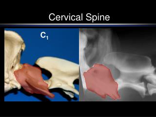
CERVICAL VERTEBRAE • Nodding and lateral flexion movements occur at the atlanto-occipital joint • Rotation of the skull occurs at the atlanto-axial joint around the dens, which acts as a pivot
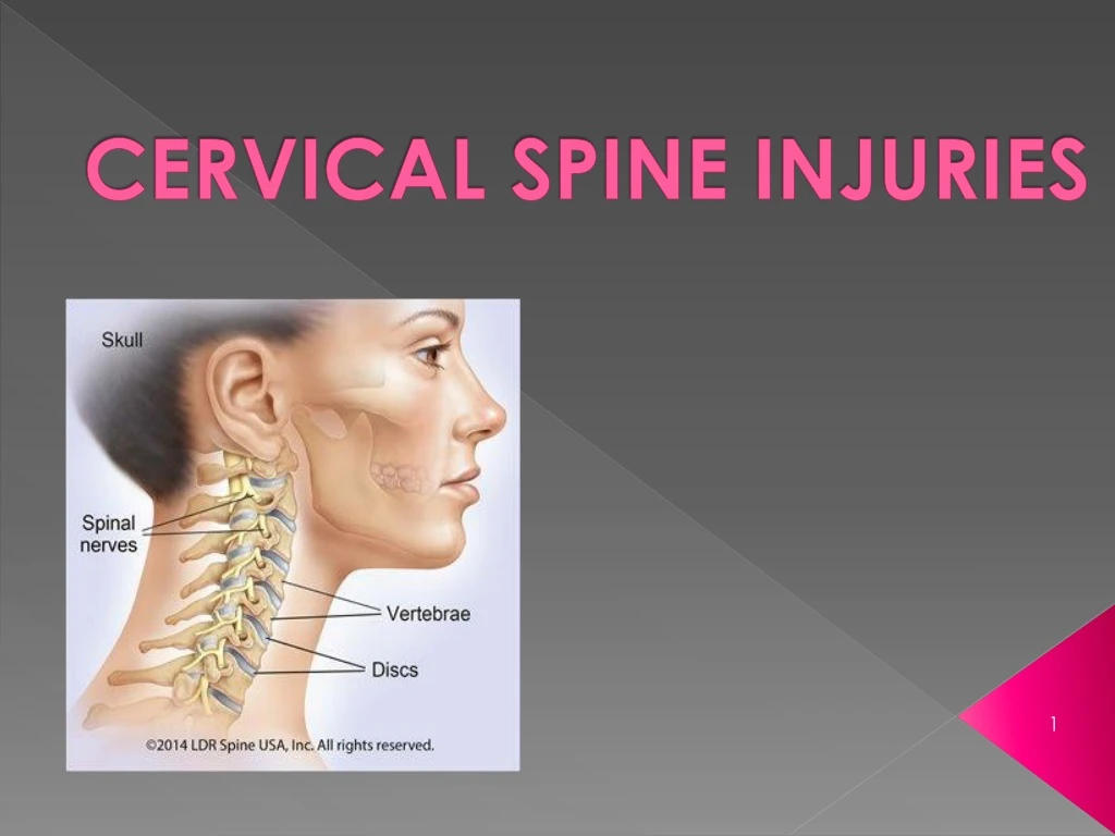
CERVICAL SPINE INJURIES • Carry a double threat: damage to the vertebral column and damage to the neural tissues • Movement may cause or aggravate the neural lesion; hence the importance of establishing whether the injury is stable or unstable and treating it as unstable until proven otherwise
STABILITY OF C-SPINE INJURIES • A Stable Injury is one in which the vertebral components will not be displaced by normal movements • In a Stable injury, if the neural elements are undamaged there is little risk of them becoming further damaged • An Unstable Injury is one in which there is a significant risk of displacement and consequent damage – or further damage – to the neural tissues
DENIS’ 3-COLUMN CONCEPT (1983) • Three structural elements must be considered: • The Posterior Osseo-ligamentous complex (or Posterior Column) consisting of the pedicles, facet joints, posterior bony arch, interspinous and supraspinous ligaments • The Middle Column comprising the posterior half of the vertebral body, the posterior part of the intervertebral disc and the posterior longitudinal ligament • The Anterior Column composed of the anterior half of the vertebral body, the anterior part of the intervertebral disc and the anterior longitudinal ligament
All fractures involving the middle column and at least one other column should be regarded as unstable • Only 10 per cent of spinal fractures are unstable • Less than 5 per cent are associated with cord damage
MECHANISM OF INJURY • Traction injury • Direct injury: Penetrating injuries to the spine, particularly from firearms and knives, are becoming increasingly common • Indirect injury: Most common cause. A variety of forces may be applied to the spine (often simultaneously): • axial compression flexion • lateral compression • flexion-rotation • Shear • flexion-distraction • Extension • Insufficiency fractures may occur with minimal force in bone which is weakened by osteoporosis or a pathological lesion
PRINCIPLES OF DIAGNOSIS ANDINITIAL MANAGEMENT • Diagnosis and management go hand in hand • Inappropriate movement and examination can irretrievably change the outcome for the worse • Early management • Airway, Breathing and Circulation • Slightest possibility of a spinal injury in a trauma patient, the spine must be immobilized until the patient has been resuscitated and other life-threatening injuries have been identified and treated.
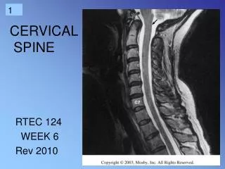
RADIOLOGY • Lateral view • Top of T1 visible • Three smooth arcs maintained • Vertebral bodies of uniform height • Odontoid intact and closely applied to C1 • AP view • Spinous processes straight and spaced equally • Intervertebral spaces roughly equal • Odontoid view • Odontoid intact • Equal spaces on either side of odontoid • Lateral margins of C1 and C2 align
Predental space – should be 3mm or less Key Things to Identify
Prevertebral soft tissue swelling May be due to hematoma from a fracture Soft tissue swelling may make fracture diagnosis difficulty
The height of the cervical vertebral bodies should be approximately equal The height of each joint space should be roughly equal at all levels Spinousprocess should be in midline and in good alignment AP View
An adequate film should include the entire odontoid and the lateral borders of C1-C2. Occipital condyles should line up with the lateral masses and superior articular facet of C1. The distance from the dens to the lateral masses of C1 should be equal bilaterally. The tips of lateral mass of C1 should line up with the lateral margins of the superior articular facet of C2. The odontoid should have uninterrupted cortical margins blending with the body of C2. Odontoid View
JEFFERSON FRACTURE • Compression fracture of the bony ring of C1, characterized by lateral masses splitting and transverse ligament tear • Mechanism: Diving into shallow water, RTA • Best seen on Odontoidview • Signs: Displacement of the lateral masses of vertebrae C1 beyond the margins of the body of vertebra C2
CT is required to define the extent of fracture • C/F: Pain in the neck usually without neurological signs. • Treatment • Stable #: (intact transverse ligament) SOFT/HARD CERVICAL COLLAR x 3 months • Unstable #: (broken transverse ligament) • SKELETAL TRACTION, HALO-VEST or SURGERY (fusion of C1-C2-C3) x 3 months
HANGMAN’S FRACTURE • Fracture through the pedicle at pars interarticularisof C2 secondary to hyperextension • Mechanism: Hanging or hitting a dashboard • Best seen on lateral view • Signs: • Prevertebral soft tissue swelling • Avulsion of anterior inferior corner of C2 associated with rupture of the anterior longitudinal ligament • Anterior dislocation of the C2 vertebral body • Bilateral C2 pars interarticularis fractures • After reduction, the neck is held in a halo-vest until union occurs. Rx: PHILADELPHIA COLLAR IMMOBILIZATION
ODONTOID FRACTURE • Fracture of the odontoid (dens) process of C2 • Best seen on the lateral view • Anderson and D’Alonzo Classification(1974) • Type I – Fracture through superior portion of dens (Stable) • Type II – Fracture through the base of the dens (most common, most dangerous, prone to non-union; Unstable; requires ORIF – worse with traction!) • Type III – Fracture that extends into the body of C2 (Stable)
BURST FRACTURE • Fracture of C3-C7 that results from axial compression • CT is required for all patients to evaluate extent of injury • Injury to spinal cord, secondary to displacement of posterior fragments, is common • Rx: RIGID IMMOBILIZATION SURGERY
CLAY SHOVELER’S FRACTURE • Fracture of a spinous process C6-T1 • Mechanism: powerful hyperflexion, usually combined with contraction of paraspinous muscles pulling on spinous processes (e.g. shoveling). Stable #. Stress # • Best seen on lateral view • Signs: • Spinous process fracture on lateral view • Ghost sign on AP view (i.e. double spinous process of C6 or C7 resulting from displaced fractured spinous process)
WEDGE FRACTURE • Compression fracture resulting from flexion • Mechanism: Hyperflexionand compression • Signs: • Buckled anterior cortex • Loss of height of anterior vertebral body • Anterosuperior fracture of vertebral body
FLEXION TEARDROP FRACTURE • Posterior ligament disruption and anterior compression fracture of the vertebral body which results from a severe flexion injury • Mechanism: hyperflexion and compression (e.g. diving into shallow water) • Best seen on lateral view • Signs: • Prevertebral swelling associated with anterior longitudinal ligament tear • Teardrop fragment from anterior vertebral body avulsion fracture • Posterior vertebral body subluxation into the spinal canal • Spinal cord compression from vertebral body displacement • Fracture of the spinousprocess
ANTERIOR SUBLUXATION • Disruption of the posterior ligamentous complex resulting from hyperflexion • Difficult to diagnose because muscle spasm may result in similar findings on the radiograph. May be stable initially, but it associates with 20%-50% delayed instability • Flexion and extension views are helpful in further evaluation. • Signs: • Loss of normal cervical lordosis • Anterior displacement of the vertebral body • Fanning of the interspinousdistance
BILATERAL FACET DISLOCATION • Complete anterior dislocation of the vertebral body resulting from extreme hyperflexion injury. It is associated with a very high risk of cord damage • Best seen on lateral view • Signs: • Complete anterior dislocation of affected vertebral body by half or more of the vertebral body AP diameter • Disruption of the posterior ligament complex and the anterior longitudinal ligament • Bow tieor bat wingappearance of the locked facets
UNILATERAL FACET DISLOCATION • Facet joint dislocation and rupture of the apophyseal joint ligaments resulting from rotatory injury of the cervical vertebrae • Best seen on lateral or oblique views • Signs: • Anterior dislocation of affected vertebral body by less than half of the vertebral body AP diameter • Discordant rotation above and below involved level • Facet within intervertebral foramen on oblique view • Widening of the disk space • Bow tie or bat wing appearance of the overriding locked facets.