Download
1 / 25
250 likes | 381 Views
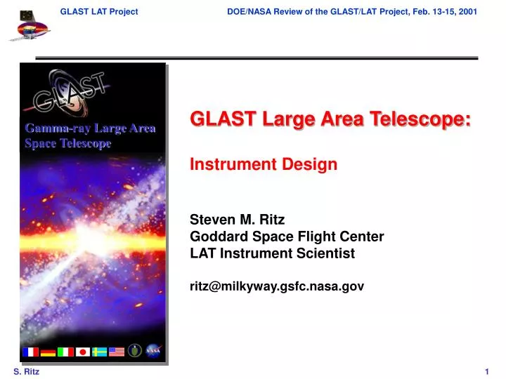
Gamma-ray Large Area Space Telescope. GLAST Large Area Telescope: Instrument Design Steven M. Ritz Goddard Space Flight Center LAT Instrument Scientist ritz@milkyway.gsfc.nasa.gov. From Science Requirements to Design. From LAT proposal Foldout D:. Simplified Flow.

E N D
Gamma-ray Large Area Space Telescope GLAST Large Area Telescope: Instrument Design Steven M. Ritz Goddard Space Flight Center LAT Instrument Scientist ritz@milkyway.gsfc.nasa.gov
From Science Requirements to Design From LAT proposal Foldout D:
Simplified Flow Science Requirements Document (SRD) Mission System Specification (MSS) Mission Assurance Requirements (MAR) Interface Requirements Document (IRD) LAT Performance Specifications Design Trade Study Space LAT Subsystem Requirements
LAT Performance Specification The LAT PS sets instrument performance requirements on: energy range and effective area energy resolution single photon angular resolution (68% and 95% containment) field of view source location determination point source sensitivity single-event time accuracy background rejection dead time gamma-ray source transient detection capabilities on board The LAT PS also includes the physical, operational and communications requirements.
Energy loss mechanisms: Pair-Conversion Telescope anticoincidence shield conversion foil particle tracking detectors e– • calorimeter • (energy measurement) e+ Experimental Technique • Instrument must measure the direction, energy, and arrivaltime of high • energy photons (from approximately 20 MeV to greater than 300 GeV): • - photon interactions with matter in GLAST • energy range dominated by pair conversion: • determinephoton direction • clear signature for background rejection - limitations on angular resolution (PSF) low E: multiple scattering => many thin layers high E: hit precision & lever arm • must detect -rays with high efficiency and reject the much higher flux (x~104) of background cosmic-rays, etc.; • energy resolution requires calorimeter of sufficient depth to measure buildup of the EM shower. Segmentation useful for resolution and background rejection.
Some Constraints (MSS & IRD) on Instrument Lateral dimension < 1.8m Restricts the geometric area. Mass < 3000 kg Primarily restricts the total depth of the CAL. Power < 650W Primarily restricts the # of readout channels in the TKR (strip pitch, # layers), and restricts onboard CPU. Telemetry bandwidth < 300 kbps orbit average Sets the required level of onboard background rejection and data volume per event. Center-of-gravity constraint restricts instrument height, but a low aspect ratio is already desirable for science. Launch loads and other environmental constraints.
Overview of LAT • 4x4 array of identical towers Advantages of modular design. • Precision Si-strip Tracker (TKR) Detectors and converters arranged in 18 XY tracking planes. Measure the photon direction. • Hodoscopic CsI Calorimeter(CAL) Segmented array of CsI(Tl) crystals. Measure the photon energy. • Segmented Anticoincidence Detector (ACD) First step in reducing the large background of charged cosmic rays. Segmentation removes self-veto effects at high energy. • Electronics System Includes flexible, highly-efficient, multi-level trigger. Systems work together to identify and measure the flux of cosmic gamma rays with energy 20 MeV - >300 GeV.
Choice of Detectors TRACKER single-sided silicon strip detectors for hit efficiency, low noise occupancy, resolution, reliability, readout simplicity. CALORIMETER hodoscopic array of CsI(Tl) crystals with photodiode readout ANTICOINCIDENCE DETECTOR segmented plastic scintillator tiles with wavelength shifting fiber/phototube readout for high efficiency and avoidance of ‘backsplash’ self-veto. for good resolution over large dynamic range; modularity matches TKR; hodoscopic arrangement allows for imaging of showers for leakage corrections and background rejection pattern recognition.
Benefits of Modularity • Construction and Test more manageable, reduce costs and schedule risk. • Early prototyping and performance tests done on detectors that are full-scale relevant to flight. • Aids pattern recognition. • Good match for triggering large-area detector with relatively localized event signatures. Issue: demonstrate that internal dead areas associated with support material and gaps between towers are not a problem. Resolution: Detailed Monte-Carlo model of instrument, combined with beam-test data of prototype hardware, used to validate design performance.
gaps, dead areas included Zoom in on a corner of the instrument scintillators front scintillators module walls First TKR module plane The instrument naturally distinguishes most cosmics from gammas, but the details are essential. A full analysis is important. gamma ray proton Design Performance Validation: LAT Monte-Carlo Model • The current LAT design is based on detailed Monte Carlo simulations. • Two years of work was put into this before any significant investment was made in hardware development. • Cosmic-ray rejection of >105:1 with high gamma ray efficiency. • Solid predictions for effective area and resolutions (computer models now verified by beam tests). Current reconstruction algorithms are existence proofs -- many further improvements under development. • Practical scheme for triggering. • Design optimization. • Simulations and analyses are all OO (C++), based on GISMO toolkit.
Monte Carlo Modeling Verified inDetailed Beam Tests Experimental setup in ESA for tagged photons: X Projected Angle 3-cm spacing, 4% foils, 100-200 MeV Data Monte Carlo GLAST Data (errors are 2) Monte Carlo See NIM A446(2000), 444; and SLAC-Pub 8682 (submitted to NIM)
1999-2000 Beam Test at SLAC Using beams of positrons, tagged photons and hadrons, with a ~flight-size tower, studies of • data system, trigger • hit multiplicities in front and back tracker sections • calorimeter response with prototype electronics. • time-over-threshold in silicon • upper limit on neutron component of ACD backsplash • hadron tagging and first look at response
Beam Test Engineering Model Flight-scale tower constructed • Beam test at SLAC in December 1999 • Balloon flight in 01 CAL and TKR have prototype custom electronics, with all functionality for flight demonstrated.
Background Rejection • Evolving understanding of the fluxes, new sources of backgrounds included. Right now: • Work is ongoing: update background fluxes and selections. L1T rate estimate being revised. • Analysis done thus far for two main reasons: • Necessary for realistic estimate of effective area. • A proof of principle, demonstration of the power of the instrument design. • Capabilities demonstrated.Next: • Optimize selections. • Some science topics may require less stringent background rejections than others.
FOV w/ energy measurement due to favorable aspect ratio Effects of longitudinal shower profiling Performance Plots (after all background rejection cuts, being updated) Derived performance parameter: high-latitude point source sensitivity (E>100 MeV), 2 year all-sky survey: 1.6x10⁻⁹ cm-2 s-1, a factor > 50 better than EGRET’s (~1x10⁻⁷ cm-2s-1).
x x x x x x • CAL: LO – independent check on TKR trigger. HI – indicates high energy event ground Instrument Triggering and Onboard Data Flow Level 3 Processing Level 1 Trigger Level 2 Processing Function: • reject background efficiently & quickly with loose cuts, • reduce computing load • remove any noise triggers Hardware trigger based on special signals from each tower; initiates readout Function: • “did anything happen?” • keep as simple as possible L3T: full instrument Function: reduce data to fit within downlink • complete event reconstruction • signal/bkgd tunable, depending on analysis cuts: :cosmic-rays~ 1:1 • TKR 3 x•y pair planes in a row** workhorse gtrigger • tracker hits ~line up • track does not point to hit ACD tile OR L2 was motivated by earlier DAQ design that had one processor per tower. Using single-tower info only, background rate reduction was typically a factor 5. On-board filtering hierarchy being redesigned. Total L3T Rate: <30 Hz> (average event size: ~7 kbits) Upon a L1T, all towers are read out within 20ms Instrument Total L1T Rate: <5 kHz> On-board science analysis: transient detection (AGN flares, bursts) rates are orbit averaged; peak L1T rate is approximately 10 kHz. L1T rate estimate being revised. **ACD may be used to throttle this rate, if req. Spacecraft
Pre-Proposal Formal Peer Reviews Subsystem designs and critical technology development decisions are periodically reviewed by independent panels that include members outside of the collaboration.
Flow into Tracker Subsystem g-ray conversion efficiency Effective Area Converter configuration Other material Effective Area Knowledge Aspect ratio Charged particle detection efficiency Geometric area Single photon angular resolution requirements Spatial measurement resolution Dead area Ionization measurement Self-trigger Field of view Data noise occupancy Trigger efficiency Bkgd rejection Dead time Trigger noise rate Dead time Total mass Trigger saturation recovery time Total power MSS&IRD requirements Environmental Tel. bndwdth
Flow into Tracker Subsystem g-ray conversion efficiency Effective Area Converter configuration Other material Effective Area Knowledge Aspect ratio Charged particle detection efficiency Geometric area Single photon angular resolution requirements Spatial measurement resolution Dead area Ionization measurement Self-trigger Field of view Data noise occupancy Trigger efficiency Bkgd rejection Dead time Trigger noise rate Dead time Total mass Trigger saturation recovery time Total power MSS&IRD requirements Environmental Tel. bndwdth
Flow into Calorimeter Subsystem Depth Energy range Geometric area Energy resolution Passive material Background rejection Spatial resolution of energy depositions Trigger signals Effective area Data noise occupancy Effective area knowledge Dynamic range Measurement dead time Dead time Total mass Total power MSS&IRD requirements Environmental Tel. bndwdth
Flow into ACD Subsystem Charged particle detection efficiency Background rejection Coverage Energy range Maximum false veto due to backsplash Noise Energy resolution CNO signals Effective area Trigger signals Effective area knowledge Deadtime Dead time Total mass Total power MSS&IRD requirements Environmental Tel. bndwdth
Flow into Electronics Subsystem Trigger Energy range Dead/live time measurement Time accuracy Data flow, deadtime Transient detection and notification Command & configuration Transient analysis and notification Effective area Environmental & Housekeeping data flow Effective area knowledge Event filtering Dead time Total mass Total power MSS&IRD requirements Environmental Tel. bndwdth
Flow into Flight Software Energy range Commanding Data flow Monitoring, reporting Transient detection and notification Calibration Event filtering Effective area Transient detection & onboard science analysis Effective area knowledge Reprogrammability Dead time Integration and Test Tel. bndwdth