Download
1 / 13
130 likes | 248 Views
MTest Facility Low Energy Beam Erik Ramberg AEM 15 October, 2007. Many thanks to Pier!!. New Capabilities of Meson Test Beam. Accelerator Division has completed the update of the MTest beamline:

E N D
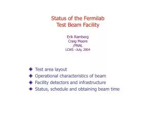
MTest Facility Low Energy BeamErik RambergAEM15 October, 2007
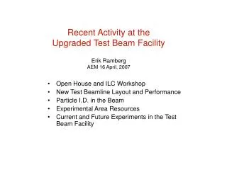
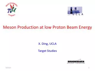
New Capabilities of Meson Test Beam • Accelerator Division has completed the update of the MTest beamline: • A new movable target was installed only 700’ upstream of the user test areas to increase low energy beam rates. The new beamline downstream of that includes 13 relocated magnets, 11 new elements, additional shielding, and movement of the beamline transversely in the tunnel. • The original upstream target was additionally put on a mover so that better primary focusing could be obtained for the downstream target. • Scintillating fiber plane monitors have been installed and debugged. • Stable low current power supplies and Hall probes were installed for better control of magnets at low current. • A 1/4” movable lead sheet was installed at the focal point to reduce electron rates when needed. • Previous test beam was limited to 4 GeV and above. The current test beam has delivered electrons down to 0.5 GeV. • New calorimetry and time-of-flight monitors were installed in the user areas. A new differential Cerenkov counter is being installed now, and a pixel telescope in the winter. • In July, taking one day away from a user request, we did a low energy scan to determine rates and beam composition.
MTest Beam Layout and Modes Movable downstream 30cm target location Movable upstream 25 cm Al target Meson Test Beam Facility Mtest secondary beamline Proton Mode: 120 GeV protons transmitted through upstream target Pion Mode: 8-66 GeV beam tuned for secondaries from upstream target Low Energy Pion Mode: 1-32 GeV beam tuned for secondaries from downstream target
MTest Detectors TOF PWC Swic Cerenkov
Time-of-flight system works below 4 GeV: • New differential Cerenkov detector can resolve beam composition at entrance to hall: • Lead glass calorimeter at end of user area can resolve beam composition there. Electron peak resolution in lead glass is ~6% at 8 GeV with collimators wide open No lead in beamline With lead in beamline
Rates* without lead scatterer Rates* with lead scatterer *Rates here are normalized to 1E11 at MW1SEM **Measured at exit of facility with PbG calorimeter
Muon vs pions at 2 GeV - preliminary results from T970 • T970 is an ILC hadron calorimeter, with RPC active planes and digital pad readout • At 2 GeV, they placed extra iron in front of their calorimeter to absorb all pions. • They showed that about 2/3 of the particles entering their calorimeter were muons and 1/3 pions. • This is first evidence for a beam at this low of an energy. • Will attempt to duplicate this at 1 GeV.
Beam profiles measured with MWPC station 1 16 GeV profiles 2 GeV profiles - We clearly need to focus on focusing.
2.5 x 2.5 meter MINERvA test detector Planned for Summer, 2008 Requests 300 MeV beam! In secondary beam In tertiary beam Doug Jensen will be overseeing this installation
Tail Catcher HCAL Electronic Racks ECAL Beam Example of CALICE Setup at MTBF Starting to write MOU now. Interference with MINERVA?
Can Fermilab Test Beam simulate ILC structure? Possible path to ILC beam structure: • Fill Main Injector with 4 Booster batches, with 19 nsec RF structure. • Turn on already existing 2.5 MHz coalescing cavities. This results in a 400 nsec particle bunch spacing, with gap after 4 buckets. • Implement a shorter partial extraction cycle (‘ping’) using current quadrupole resonance magnet. • Fit 5 of these pings in a 1 second spill . . . x100 1 second
Many thanks to Accelerator Division for their efforts Peter Prieto in front of pulsing circuit for QXR QXR quadrupole in Main Injector Fast pulse performance in Tevatron - 1997