Download
1 / 9
90 likes | 204 Views
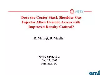
This research analyzes the role of the center stack shoulder gas injector in enhancing H-mode access and improving density control in the NSTX tokamak. Observations indicate that the injector facilitates a controlled, non-disruptive density rise during long H-mode pulses. The time dependence of density rises aligns with decay times from the midplane injector, suggesting effective control of edge density buildup. Proposed experiments aim to optimize fueling rates and assess the impact of various injector locations on plasma performance, indicating a need for further investigation into neutral trapping mechanisms.

E N D
Does the Center Stack Shoulder Gas Injector Allow H-mode Access with Improved Density Control? R. Maingi, D. Mueller NSTX XP Review Dec. 23, 2003 Princeton, NJ
ne [1019m-3] #108728 0.710 sec 0.460 sec 0.260 sec SNBI Sgas dNe/dt 0.227 sec Uncontrolled (non-disruptive) density rise in long pulse H-modes • Edge density builds and diffuses in • Time dependence of density rise similar to center stack midplane injector decay time #108728 Ip [MA] PNBI/10 [MW] ne [1019 m-3] Da [au] [torr-l/s] WMHD*10 [MJ] H98pby2
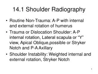
Gas Injectors Graphite tiles ParametersDesignAchieved Major Radius 0.85m Minor Radius 0.67m Plasma Current 1MA1.5MA Toroidal Field 0.6T0.6T Heating and Current Drive NBI (100keV) 5MW7 MW RF (30MHz) 6MW6 MW Wall Conditioning: ~350 deg. bakeout of graphite tiles Regular boronization (~3 weeks) Helium Glow between discharges Center stack gas injection Passive stabilizing plates NSTX Explores Low Aspect Ratio (A=R/a) physics regime }A ≥ 1.27
Load-and-Dump Gas Injectors Have Different Flow Characteristics and Delay Time
CS Mid LFS CS Top L-H Center-stack Midplane Gas Injector Fueling Has Lower PL-H Than LFS and CS Top in LSN shape • Experiment run • when L-H • power threshold • was ~ 1-2 NBI src • (start of run 2003) • Note LFS shot and • CS tophad no L-H • -> higher PL-H R~1.48m
CS mid, LSN 109866@0.2s LFS top, LSN 109875@0.201s CS top, LSN 109869@0.2s X-point+LFS top, LSN 109884@0.2s CS top, USN 109877@0.2s CS top, DN 109885@0.2s Unfiltered Recycling Light Pattern Changes with Gas Injector Location and Plasma Shape LSN=lower single null; USN=upper single null; DN=double null
CS Mid LFS CS Top CS shoulder injector enabled H-mode access and reasonable performance in double-null configuration • LH time delayed with CS shoulder (wall conditions different or plasma physics?)
Proposed Run Plan (1 day) Hypothesis: neutral trapping differences lead to better H-mode access in DN than LSN (is USN even better?), due to LFS neutrals higher rotation drag (-> need ERD data!) • Restore long pulse DN center stackmidplane fueled discharge, e.g. #109828 (#109004?) or a more recent discharge, if available (Ip = 1 MA, Bt = 0.45 T). (2 shots) • Scan plenum pressure from 600-1500 torr in 3-4 steps, 10 min. HeGDC between shots. Increase HeGDC time for the highest flow rate to 12-15 minutes if base pressure increased substantially. (5 shots) • Switch to center stack shoulder fueling, and scan plenum pressure from 300-800. Increase HeGDC time for the highest flow rate to 12-15 minutes if base pressure increased substantially. (8 shots)
Proposed Run Plan (1 day) • Using the “best” fueling rate from above (which allowed e.g. longest H-mode with lowest density rise), perform drsep variation to +/- 1 cm (or larger?) to determine if neutral trapping is different in the three configurations. Start from #108476, which ramped drsep from 0.2 – 1.0 cm from a balanced DN. (6 shots) • Repeat above with a lower fueling rate and a higher fueling rate. Increase HeGDC time for the highest flow rate to 15 minutes if base pressure increased substantially (12 shots) • This experiment should only be run when long pulse H-modes have already been re-obtained with the center stack midplane injector. The capability to switch between injectors without a controlled access is a requirement.