Download
1 / 11
110 likes | 137 Views
Explore the organization of OSI layers, function of interfaces, encapsulation, and roles of physical and data link layers in networking. Learn about passing data between devices.

E N D
Interfaces Between Layers The passing of the data and network information down through the layers of the sending device and back up through the layers of the receiving device is made possible by an interface between each pair of adjacent layers. Each interface defines the information and services a layer must provide for the layer above it. Well-defined interfaces and layer functions provide modularity to a network. As long as a layer provides the expected services to the layer above it, the specific implementation of its functions can be modified or replaced without requiring changes to the surrounding layers.
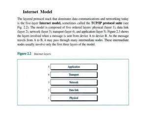
Organization of the Layers The seven layers can be thought of as belonging to three subgroups. Layers I, 2, and 3-physical, data link, and network-are the network support layers; they deal with the physical aspects of moving data from one device to another (such as electrical specifications, physical connections, physical addressing, and transport timing and reliability). Layers 5, 6, and 7-session, presentation, and application-can be thought of as the user support layers; they allow interoperability among unrelated software systems. Layer 4, the transport layer, links the two subgroups and ensures that what the lower layers have transmitted is in a form that the upper layers can use.
Encapsulation Figure 2.3 reveals another aspect of data communications in the OSI model: encapsulation. A packet (header and data) at level 7 is encapsulated in a packet at level 6. The whole packet at level 6 is encapsulated in a packet at level 5, and so on.
Physical Layer The physical layer coordinates the functions required to carry a bit stream over a physical medium. It deals with the mechanical and electrical specifications of the interface and transmission medium. It also defines the procedures and functions that physical devices and interfaces have to perform for transmission to Occur. Figure 2.5 shows the position of the physical layer with respect to the transmission medium and the data link layer.
The physical layer is also concerned with the following: • Physical characteristics of interfaces and medium. • Representation of bits. • Data rate. • Synchronization of bits. • Line configuration. • Physical topology. • Transmission mode.
Data Link Layer The data link layer transforms the physical layer, a raw transmission facility, to a reliable link. It makes the physical layer appear error-free to the upper layer (network layer). Figure 2.6 shows the relationship of the data link layer to the network and physical layers.
Framing. • Flow control. • Error control. • . Access control.