Target Engagement
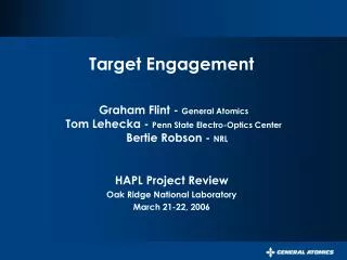
Target Engagement. Graham Flint - General Atomics Tom Lehecka - Penn State Electro-Optics Center Bertie Robson - NRL. HAPL Project Review Oak Ridge National Laboratory March 21-22, 2006. Overall Concept for Target Engagement in a Semi-Rigid Environment. Coincidence sensors. Focusing

Target Engagement
E N D
Presentation Transcript
Target Engagement Graham Flint - General Atomics Tom Lehecka - Penn State Electro-Optics CenterBertie Robson - NRL HAPL Project Review Oak Ridge National Laboratory March 21-22, 2006
Overall Concept for Target Engagement in a Semi-Rigid Environment Coincidence sensors Focusing mirrors Target glint source Segmented vacuum window • Offset target is illuminated in flight by a Q-switched glint laser. • Each coincidence sensor views the glint via the rear surface of a wedged dichroic mirror. • Disparities between beamlet alignment and glint signals are used to reposition the fast-steering mirrors. • Coincidence sensors verify pointing of redirected beamlets. Dichroic mirror Chamber N-S axis Amplifier / multiplexer/fast steering mirrors ASE Source Offset Target Alignment Laser Cat’s eye retroreflectors • Slow steering mirrors in the amplifier chain continuously center each alignment beamlet upon its coincidence sensor. Wedged dichroic mirrors Target injection / tracking subsystem Grazing incidence mirrors • Integrated injection / tracking subsystem places the target within a defined volume which is centered upon the chamber’s nominal center.
Geometric Correction associated with a Single Glint Reference Source Chamber axis r Glint offset /2 a Target • Beamlet displacement from chamber axis: • Glint offset: a = r sin /2 • For negligible offset error (as π): a < 5 m • For IFE ( r = 2.35 mm): r/r ≤ 0.2% • Current specification: r/r ≤ 1.0%
Null-Referenced In-Flight Measurement of Target Diameter, Transit Time and Velocity Detector mask Target Trajectory Detector #1 Signal #1 Time Monochromatic Illumination Source 10X Telecentric Objective Detector #2 Signal #2 Time t • Assumed target velocity 100 ms-1 • Image velocity (10x) 1000 ms-1 • Mask slit width 25 m • Transit time precision < 25 nsec • Corresponding diametric precision < 0.1% • Requirement for glint offset correction 0.2% • Velocity determination precision(0.5 m separation) ~ 10-5 • Target placement precision ~ 100 m
Coincidence Sensor Views Target Glint via Common Footprint on Grazing Incidence Mirror Beamlet Target glint source Dichroic mirror Grazing incidence mirror Target at t = 0 Wedge angle ~ 1 mrad Target at t = -1.2 ms • Dichroic mirror has long wavelength pass first surface, high reflecting rear surface. • Mirror wedge angle compensates for combination of targetoffset and glint parallax. • Except for monolithic dichroic mirror, main laser and coincidence sensor share a common optical path. • Common path eliminates sensitivity to vibration at frequencies below ~50 Hz. Target injection / Tracking subsystem
Coincidence Sensor / Retroreflector Schematic and Performance Alignment laser beam Vacuum window Cat’s eye retroreflector 10X Microscope objective Position Sensitive Detector Virtual return from beamlet LWP blocking filter Coincidence Sensor Target glint return Main beamlet • Sensor clear aperture 100 mm • Sensor effective focal length 15 m • Sensor field at chamber center 4.5 mm X 4.5 mm • Target-to-beamlet error (1 ) 24 m • 3.2 collective centroid error (48 beamlets) 11 m
End-to-end Target Engagement Strategy TARGET LAUNCH (MECH. / EM SLING SHOT) DEMONSTRATED PERFORMANCE (MECHANICAL) I TARGET TRACKING POISSON SPOT (X & Y AXES) CROSSING SENSOR/ OPTICAL DOPPLER (Z AXIS) II ELECTROSTATIC FINE STEERING VOLTAGE PREC - 10-2) POST-STEERING TRAJECTORY PRECISION COINCIDENCE SENSOR FIELD OF VIEW (PRECISION -10-2) FAST STEERING MIRROR COMMAND PRECISION BEAMLET STEERING MAXIMUM EXCURSION (PREC. -10-2) BEAMLET POINTING PRECISION III SINGLE BEAMLET ENGAGEMENT PRECISION COLLECTIVE BEAMLINE CENTROID PRECISION 10-7 10-6 10-5 10-4 10-3 Precision ( 99.9 % CONFIDENCE LEVEL ) 1 3.2