Review: Sequential Definitions
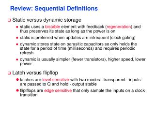
Review: Sequential Definitions. Static versus dynamic storage static uses a bistable element with feedback ( regeneration ) and thus preserves its state as long as the power is on static is preferred when updates are infrequent (clock gating)

Review: Sequential Definitions
E N D
Presentation Transcript
Review: Sequential Definitions • Static versus dynamic storage • static uses a bistable element with feedback (regeneration) and thus preserves its state as long as the power is on • static is preferred when updates are infrequent (clock gating) • dynamic stores state on parasitic capacitors so only holds the state for a period of time (milliseconds) and requires periodic refresh • dynamic is usually simpler (fewer transistors), higher speed, lower power • Latch versus flipflop • latches are level sensitive with two modes: transparent - inputs are passed to Q and hold - output stable • fliplflops are edge sensitive that only sample the inputs on a clock transition
In Out D Q clock clock time tsu thold In data stable time tc-q Out output stable output stable time Review: Timing Metrics
Review: System Timing Constraints Inputs Outputs Combinational Logic Current State Next State State Registers T (clock period) clock tcdreg + tcdlogic thold T tc-q + tplogic + tsu
!clk clk QM T1 I1 T2 I2 D Q C1 C2 clk !clk mastertransparent slave hold clk !clk masterhold slave transparent Dynamic ET Flipflop master slave tsu = thold = tc-q = tpd_tx zero 2 tpd_inv + tpd_tx
Dynamic ET FF Race Conditions !clk clk QM T1 I1 T2 I2 D Q C1 C2 clk !clk 0-0 overlap race condition toverlap0-0 < tT1 +tI1 + tT2 clk !clk 1-1 overlap race condition toverlap1-1 < thold
mastertransparent slave hold masterhold slave transparent Dynamic Two-Phase ET FF clk1 clk2 QM T1 I1 T2 I2 D Q C1 C2 !clk1 !clk2 clk1 tnon_overlap clk2
Pseudostatic Dynamic Latch • Robustness considerations limit the use of dynamic FF’s • coupling between signal nets and internal storage nodes can inject significant noise and destroy the FF state • leakage currents cause state to leak away with time • internal dynamic nodes don’t track fluctuations in VDD that reduces noise margins • A simple fix is to make the circuit pseudostatic !clk D clk • Add above logic added to all dynamic latches
Master Slave M2 M6 clk on !clk off M4 M8 QM on off Q D on C1 clk off C2 !clk M3 M7 on off M1 M5 master transparent slavehold clk !clk masterhold slavetransparent C2MOS (Clocked CMOS) ET Flipflop • A clock-skew insensitive FF
clk clk !clk !clk C2MOS FF 0-0 Overlap Case • Clock-skew insensitive as long as the rise and fall times of the clock edges are sufficiently small M2 M6 0 0 M4 M8 QM Q D C1 C2 M1 M5
clk clk !clk !clk C2MOS FF 1-1 Overlap Case M2 M6 QM Q D 1 C1 1 C2 M3 M7 M1 M5 1-1 overlap constraint toverlap1-1 < thold
C2MOS Transient Response For a 0.1 ns clock QM(3) Q(3) Volts Q(0.1) clk(0.1) For a 3 ns clock (race condition exists) clk(3) Time (nsec)
True Single Phase Clocked (TSPC) Latches Negative Latch Positive Latch Q clk clk In In clk clk Q hold when clk = 1 transparent when clk = 0 transparent when clk = 1 hold when clk = 0
Master Slave on on on on on on clk Q clk D off off off off QM off off clk clk mastertransparent slavehold clk masterhold slavetransparent TSPC ET FF
off on 1 D clk D M3 M6 M9 on !D off QM off on Q clk D M2 X clk M5 off M8 on clk M1 M4 M7 mastertransparent slavehold clk masterhold slavetransparent Simplified TSPC ET FF
Sizing Issues in Simplified TSPC ET FF clk !Qmod Transistor sizing Original width M4, M5 = 0.5m M7, M8 = 2m Modified width M4, M5 = 1m M7, M8 = 1m !Qorig Volts Qorig Qmod Time (nsec)
Split-Output TSPC Latches Negative Latch Positive Latch Q A In clk clk In A Q transparent when clk = 1 hold when clk = 0 hold when clk = 1 transparent when clk = 0 When In = 0, A = VDD - VTn When In = 1, A = | VTp |
clk Split-Output TSPC ET FF clk D QM clk Q
0/Vdd ON/OFF OFF 0 1 ON clk 1/0 P1 P3 Vdd Q X OFF OFF M3 M6 ON ON 1/0 ON/ OFF D M2 P2 M5 1 1 0 1 ON M1 M4 ON !clkd 0 OFF Pulsed FF (AMD-K6) • Pulse registers - a short pulse (glitch clock) is generated locally from the rising (or falling) edge of the system clock and is used as the clock input to the flipflop • race conditions are avoided by keeping the transparent mode time very short (during the pulse only) • advantage is reduced clock load; disadvantage is substantial increase in verification complexity
D M9 M2 M5 M7 Q M1 M4 !Q M6 M8 M3 M10 clk Sense Amp FF (StrongArm SA100) • Sense amplifier (circuits that accept small swing input signals and amplify them to full rail-to-rail signals) flipflops • advantages are reduced clock load and that it can be used as a receiver for reduced swing differential buses 0 1 1 1 0 1 1 1 0 0 1
Choosing a Clocking Strategy • Choosing the right clocking scheme affects the functionality, speed, and power of a circuit • Two-phase designs • + robust and conceptually simple • - need to generate and route two clock signals • - have to design to accommodate possible skew between the two clock signals • Single phase designs • + only need to generate and route one clock signal • + supported by most automated design methodologies • + don’t have to worry about skew between the two clocks • - have to have guaranteed slopes on the clock edges