Download
1 / 31
410 likes | 1.03k Views
Advanced Active Matrix OLED Technologies. Steven A. Van Slyke Display and Components OLED Modules Business Unit Eastman Kodak Company Rochester, New York, USA. Outline. Methods of Color Patterning Discussion of RGBW Format RGBW in imaging applications Display Prototypes with RGB and RGBW

E N D
Advanced Active Matrix OLED Technologies Steven A. Van Slyke Display and Components OLED Modules Business Unit Eastman Kodak Company Rochester, New York, USA
Outline • Methods of Color Patterning • Discussion of RGBW Format • RGBW in imaging applications • Display Prototypes with RGB and RGBW • White chemistry and formulation • Display designs • Processing and testing • Power consumption of RGB and RGBW displays • Importance of emitter white point • Color filter array • Operational Stability • Conclusions
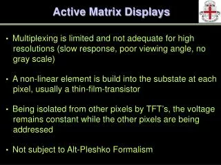
Methods of Color Patterning(illustrated for bottom emitting) Patterned RGB Emitting Layers Cathode • Disadvantages • Typically uses shadow masking for RGB patterning (yield, cost, scaleability) • Aperture ratio issues (shadow mask) • Differential aging of RGB • Advantages • High efficiency • Good color ETL Emitting Layer HTL Anodes Substrate RGB White-Emitting Layer with RGB Color-Filter Array • Advantages • Unpatterned emitting layer (no masks) • Aperture ratio not affected by RGB patterning • Enabled by high efficiency white • Fewer OLED processing steps • Reduced differential aging (white is very stable) • Disadvantages • Loss of efficiency due to filter absorption • Gamut controlled by white spectrum White- Emitting Layer W-RGB
Shadow Masking in Manufacturing • Precision alignment subsystems: +/-3 µm in production • Tolerances across a 335 x 550 mm substrate: +/-15 µm • Significant concerns • thermal expansion • contact with (fragile) substrate • cleaning without damage • ability to scale to large substrates • COST Tapered Mask Eliminates Non-Uniformity Within Pixel
Sony Clie PEG-VZ90 LTPS (480 x 320) (Multi-media handheld) Examples of RGB and White -> RGB Displays(AMOLED) ProductsPrototype RGB direct patterned White with RGB color filters Kodak / Sanyo LTPS 2.2 ” Kodak LS633 LTPS (521 x 218) 15 ” 3.8 ” 2.2 ” Neosol PMP LTPS (521 x 218)
Methods of Color Patterning(illustrated for bottom emitting) RGBW White-Emitting Layer with RGBW Color-Filter Array • Advantages • Unpatterned emitting layer (no masks) • High efficiency white sub- pixel results in significantpower reduction (a large portion of image content contains white) • Enabled by high efficiency white • Disadvantages • Loss of efficiency due to filter absorption White- Emitting Layer W-RGBW
RGB and RGBW Formats (with W emitter) RGBW Format RGB Format 12.5 cd/A 12.5 cd/A White OLED Color Filter Array Device Emission Approximate Efficiencies(cd/A) 2.6 6.6 1.1 2.6 6.6 1.1 12.5 All sub-pixels filtered White sub-pixel unfiltered(display efficiency gain) Takes advantage of high efficiency, stable white For imaging, takes advantage of fact that most images are very unsaturated (the world is gray)
RGB and RGBW – primary colors R G B R G B W Red Green Blue White Shown for NTSC colorsand D65 white.
RGB and RGBW – unsaturated colors Emitting sub-pixels RGB RGBW Red White Green Green Blue Blue Red Red Green Green Blue White Red Red Green White Blue Blue Shown for NTSC colorsand D65 white.
Probability in DSC Images 1931 CIEY 1931 CIEX Importance of Neutral Colors in Imaging Based on 13,000 Digital Still Camera Images Probability in DSC Images (based on 13,000 images)
Display Power Consumption for RGB and RGBWAssumes W is fully utilized to reduce power For 13,000 DSC images, color saturation ~50% C = 100% RGBW / RGB power consumption C = 0% RGBW RGB Color Saturation
Outline • Methods of Color Patterning • Discussion of RGBW Format • RGBW in imaging applications • Display Prototypes with RGB and RGBW • White chemistry and formulation • Display designs • Processing and testing • Power consumption of RGB and RGBW displays • Importance of emitter white point • Color filter array • Operational Stability • Conclusions
White OLED Layer Structure used for Prototypes LiF / Al Cathode Alq Electron Transporting Layer Blue Emitting Layer Yellow Emitting Layer NPB Hole Transport Layer Hole Injection Layer ITO Anode Substrate Note: Better power efficiency resultsif white point of emitter = D65
RGB and RGBW AMOLED Test Layouts2.2”diagonal 198 x 66 u sub-pixel size . . . . . . . . . . . . . . . . RGB RGBW . . . . . . . . . . . . . . . . . . . . 528 columns (176 x RGB) 528 columns (132 x RGBW) 220 rows 38720 pixels (RGB) (RGB = SQUARE) 116160 sub-pixels 29040 pixels (RGBW = RECTANGULAR) 116160 sub-pixels
RGB and RGBW Test Layouts2.2”diagonal 198 x 66 u sub-pixel size 176(RGB) x 220 RGB Pixel = 198 u x 198 u 2.2 inch diagonal 132(RGBW) x 220 Note that this is a test format only.A better comparison would be with 176(RGBW) x 220. RGBW Pixel = 264 u x 198 u
Prototype Process Flow = AMOLED - RGB Color Filter Array = AMOLED - RGBW Color Filter Array Coat organic and Cathode layers Scribe / break Test 6” x 6” substratewith four 2.2” displays • Identical white formulation used for • both RGB and RGBW
Prototype Characteristics Note: Efficiency and colorsdepend on color filter selection.
NOTE: Standard Two-Transistor Design Used Data Storage Capacitor (keeps Vg constant during frame time) Power Line(Vdd = 13 volts) Data Line Row Scan Line Capacitor Line Write Transistor (acts as switch to allow data to be written to power transistor) OLED Power TransistorVg level controls gray scale Common Cathode (unpatterned cathode film common to all pixels) Data Line (applies voltage to power transistor gate)
Test Methodology • Determine luminance-current-chromaticity characteristics for each color channel (R,G,B, and W) • Display images that have been appropriately processed for RGB and RGBW displays • Measure the total panel current for each image • Calculate the power consumption for each image • Power = Panel current x 13 volts • Compare power consumption of devices • RGB vs. RGBW (Note: these are both with white emitter / color filter arrays)
RGBW Display Display “off” Display “on” Display “off”
RGB and RGBW Displays RGB 176 (RGB) x 220 RGBW 132 (RGBW) x 220
RGB and RGBW Displays RGB 176 (RGB) x 220 RGBW 132 (RGBW) x 220 22
Outline • Methods of Color Patterning • Discussion of RGBW Format • RGBW in imaging applications • Display Prototypes with RGB and RGBW • White chemistry and formulation • Display designs • Processing and testing • Power consumption of RGB and RGBW displays • Importance of emitter white point • Color filter array • Operational Stability • Conclusions
RGB and RGBW Power Consumption2.2” diagonal, 100cd/m2 white after 44% T circular polarizer W-RGB W-RGBW Average for 13,000 images: 180 mW - RGBW 340 mW - RGB
Importance of Emitter White = Display White Relative white emitter efficiency (cd/A) to attain equal RGBW display power. Target display white point = D65 ★ = D65 Conclusion – very important that emitter white is close to display white point for lowest power consumption.
Conclusions – Power Consumption • The RGBW format requires ½ the power compared to the RGB format – agrees with model prediction. • If the emitter white point is not at the display white point, (D65), the efficiency (cd/A) needs to be higher for equivalent power consumption.
Outline • Methods of Color Patterning • Discussion of RGBW Format • RGBW in imaging applications • Display Prototypes with RGB and RGBW • White chemistry and formulation • Display designs • Processing and testing • Power consumption of RGB and RGBW displays • Importance of emitter white point • Color filter array • Operational Stability • Conclusions
Operational Stability White Channel Test condition: white sub-pixels operated Note: Aperture ratio = 0.285 White ratio = 0.25 Fraction emitting = 0.0713
Operational Stability Model Results • AMOLED Stability Modeling • Inputs: • Display Luminance • Target white point • Color filter properties • Contrast filter properties • White stability at various current densities • White emission spectrum • White efficiency • Aperture ratio limits • Average DSC images • Outputs: • Average current density • Lifetime estimate • For the display in this presentation, average current density = 7.3 mA/cm2. • Stability (T1/2) estimated at ~13,000 hrs. • 180 cd/m2 peak white with 44% T polarizer • DSC images
Conclusions • RGBW displays require ½ the power as analogous RGB displays for imaging applications, with no loss in gamut. • Operational stability of RGBW displays is excellent, and is ~ same as RGB displays. • For optimum power consumption, it is important that the white emission is close to the target display white point (e.g. D65).
Acknowledgements Eastman Kodak Company Paula Alessi, Andy Arnold, John Burtis, Peter Castro, T.K. Hatwar, Mark Hettel, Paul Kane, Mike Miller, Mike Murdoch, Terry O’Toole, G. Rajeswaran, Jeff Spindler, Dave Williams SANYO Electric Company K. Mameno, R. Nishikawa, T. Omura, S. Matsumoto