Download
1 / 36
370 likes | 582 Views
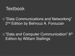
Semiconductor Device Physics. Textbook and Syllabus. Textbook: “Semiconductor Device Fundamentals”, Robert F. Pierret, International Edition, Addison Wesley, 1996. Syllabus: Chapter 1: Semiconductors: A General Introduction Chapter 2: Carrier Modeling Chapter 3: Carrier Action

E N D
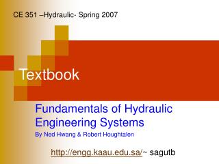
Semiconductor Device Physics Textbook and Syllabus Textbook: “Semiconductor Device Fundamentals”, Robert F. Pierret, International Edition, Addison Wesley, 1996. Syllabus: Chapter 1: Semiconductors: A General Introduction Chapter 2: Carrier Modeling Chapter 3: Carrier Action Chapter 5: pn Junction Electrostatics Chapter 6: pn Junction Diode: I–V Characteristics Chapter 7: pn Junction Diode: Small-Signal Admittance Chapter 8: pn Junction Diode: Transient Response Chapter 14: MS Contacts and Schottky Diodes Chapter 9: Optoelectronic Diodes Chapter 10: BJT Fundamentals Chapter 11: BJT Static Characteristics Chapter 12: BJT Dynamic Response Modeling
Grade Policy Semiconductor Device Physics Final Grade = 15% Homework + 15% Quizzes + 30% Midterm Exam + 40% Final Exam + Extra Points • Homeworks will be given in fairly regular basis. The average of homework grades contributes 10% of final grade. Tests will be given to validate the submitted homeworks. • Homeworks are to be written on A4 papers, otherwise they will not be graded. • Homeworks must be submitted on time, one day before the schedule of the lecture. Late submission will be penalized by point deduction of –10·n, where n is the total number of lateness made. • There will be 3 quizzes. Only the best 2 will be counted. The average of quiz grades contributes 20% of final grade. • The maximum lateness in coming to class is 25 minutes, otherwise attendance will not be counted.
Grade Policy Semiconductor Device Physics Semiconductor Device PhysicsHomework 2Ito Chen00920170000821 March 2021D6.2. Answer: . . . . . . . . • Heading of Homework Papers (Required) • Midterm and final exams follow the schedule released by AAB (Academic Administration Bureau). • Make up of quizzes must be held within one week after the schedule of the respective quiz. • Make up for mid exam and final exam must be requested directly to AAB.
Semiconductor Device Physics Grade Policy • In order to maintain the integrity, the score of a make up quiz or exam can be multiplied by 0.9 (i.e., the maximum score for a make up will be 90). • Extra points will be given every time you solve a problem in front of the class or answer a question. You will earn 1 or 2 points. • Lecture slides can be copied during class session. The updated version will be available on the lecture homepage around 1 day after class schedule. Please check regularly. http://zitompul.wordpress.com • The use of internet for any purpose during class sessions is strictly forbidden. • You are expected to write a note along the lectures to record your own conclusions or materials which are not covered by the lecture slides.
Semiconductor Device Physics Greek Alphabet • new • zz-eye • pie • taw • fie • k-eye • sigh • mew
Semiconductor Device Physics Chapter 1 Semiconductors: A General Introduction
Chapter 1 Semiconductors: A General Introduction What is a Semiconductor? • Low resistivity “conductor” • High resistivity “insulator” • Intermediate resistivity “semiconductor” • The conductivity (and at the same time the resistivity) of semiconductors lie between that of conductors and insulators.
Chapter 1 Semiconductors: A General Introduction No recognizable long-range order Entire solid is made up of atoms in an orderly three- dimensional array Completely ordered in segments What is a Semiconductor? • Semiconductors are some of the purest solid materials in existence, because any trace of impurity atoms called “dopants” can change the electrical properties of semiconductors drastically. • Unintentional impurity level: 1 impurity atom per 109 semiconductor atom. • Intentional impurity ranging from 1 per 108 to 1 per 103. polycrystalline amorphous crystalline • Most devices fabricated today employ crystalline semiconductors.
Chapter 1 Semiconductors: A General Introduction Semiconductor Materials Elemental:Si, Ge, C Compound: IV-IV SiC III-V GaAs, GaN II-VI CdSe Alloy: Si1-xGex AlxGa1-xAs As : ArsenicCd : CadmiumSe : SeleniumGa : Gallium
Chapter 1 Semiconductors: A General Introduction From Hydrogen to Silicon
Chapter 1 Semiconductors: A General Introduction The Silicon Atom • 14 electrons occupying the first 3 energy levels: • 1s, 2s, 2p orbitals are filled by 10 electrons. • 3s, 3p orbitals filled by 4 electrons. • To minimize the overall energy, the 3s and 3p orbitals hybridize to form four tetrahedral 3sp orbital. • Each has one electron and is capable of forming a bond with a neighboring atom.
Chapter 1 Semiconductors: A General Introduction The Si Crystal • Each Si atom has 4 nearest neighbors. • Atom lattice constant(length of the unit cell side) • a = 5.431A, 1A=10–10m ° ° • Each cell contains: 8 corner atoms 6 face atoms 4 interior atoms a “Diamond Lattice”
Chapter 1 Semiconductors: A General Introduction How Many Silicon Atoms per cm–3? • Number of atoms in a unit cell: • 4 atoms completely inside cell • Each of the 8 atoms on corners are shared among 8 cells count as 1 atom inside cell • Each of the 6 atoms on the faces are shared among 2 cells count as 3 atoms inside cell • Total number inside the cell = 4 + 1 + 3 = 8 • Cell volume = (.543 nm)3 = 1.6 x 10⁻²²cm3 • Density of silicon atom • = (8 atoms) / (cell volume) • = 5 × 10²² atoms/cm3 • What is density of silicon in g/cm3?
Chapter 1 Semiconductors: A General Introduction Compound Semiconductors • “Zincblende” structure • III-V compound semiconductors: GaAs, GaP, GaN, etc.
Chapter 1 Semiconductors: A General Introduction Crystallographic Notation Miller Indices h: inverse x-intercept of plane k: inverse y-intercept of plane l: inverse z-intercept of plane (h, k and l are reduced to 3 integers having the same ratio.)
Chapter 1 Semiconductors: A General Introduction Crystallographic Planes _ (632) plane (001) plane (221) plane
Chapter 1 Semiconductors: A General Introduction Crystallographic Planes
Chapter 1 Semiconductors: A General Introduction Crystallographic Planes of Si Wafers • Silicon wafers are usually cut along a {100} plane with a flat or notch to orient the wafer during integrated-circuit fabrication. • The facing surface is polished and etched yielding mirror-like finish.
Chapter 1 Semiconductors: A General Introduction Crystal Growth Until Device Fabrication
Chapter 1 Semiconductors: A General Introduction Unit cell: View in <110> direction View in <100> direction Crystallographic Planes of Si View in <111> direction
Chapter 2 Carrier Modeling
Chapter 2 Carrier Modeling Electronic Properties of Si • Silicon is a semiconductor material. • Pure Si has a relatively high electrical resistivity at room temperature. • There are 2 types of mobile charge-carriers in Si: • Conduction electrons are negatively charged, e=–1.602 10–19 C • Holes are positively charged, p=+1.602 10–19C • The concentration (number of atom/cm3) of conduction electrons & holes in a semiconductor can be influenced in several ways: • Adding special impurity atoms (dopants) • Applying an electric field • Changing the temperature • Irradiation
Chapter 2 Carrier Modeling Si Si Si Si Si Si Si Si Si Bond Model of Electrons and Holes • 2-D Representation Hole • When an electron breaks loose and becomes a conduction electron, then a hole is created. Conductionelectron
Chapter 2 Carrier Modeling What is a Hole? • A hole is a positive charge associated with a half-filled covalent bond. • A hole is treated as a positively charged mobile particle in the semiconductor.
Chapter 2 Carrier Modeling Conduction Electron and Hole of Pure Si • Covalent (shared e–) bonds exists between Si atoms in a crystal. • Since the e– are loosely bound, some will be free at any T, creating hole-electron pairs. ni≈ 1010 cm–3 at room temperature ni= intrinsic carrier concentration
Chapter 2 Carrier Modeling Si: From Atom to Crystal Energy states (in Si atom) Energy bands (in Si crystal) • The highest mostly-filled band is the valence band. • The lowest mostly-empty band is the conduction band.
Chapter 2 Carrier Modeling Energy Band Diagram Energy Band Diagram Ec EG, band gap energy Electron energy Ev • For Silicon at 300 K, EG = 1.12 eV • 1 eV = 1.6 x 10⁻¹⁹ J • Simplified version of energy band model, indicating: • Lowest possible conduction band energy (Ec) • Highest possible valence band energy (Ev) • Ec and Ev are separated by the band gap energy EG.
Chapter 2 Carrier Modeling Measuring Band Gap Energy • EGcan be determined from the minimum energy (hn) of photons that can be absorbed by the semiconductor. • This amount of energy equals the energy required to move a single electron from valence band to conduction band. Electron Ec Photon photon energy: hn= EG Ev Hole Band gap energies
Chapter 2 Carrier Modeling Carriers • Completely filled or empty bands do not allow current flow, because no carriers available. • Broken covalent bonds produce carriers (electrons and holes) and make current flow possible. • The excited electron moves from valence band to conduction band. • Conduction band is not completely empty anymore. • Valence band is not completely filled anymore.
Chapter 2 Carrier Modeling E v E c Band Gap and Material Classification E c = E ~8 eV G E c = E 1.12 eV E G c E E E v v v Metal Si SiO2 • Insulators have large band gap EG. • Semiconductors have relatively small band gap EG. • Metals have very narrow band gap EG . • Even, in some casesconduction band is partially filled,Ev > Ec.
Chapter 2 Carrier Modeling Carrier Numbers in Intrinsic Material • More new notations are presented now: • n : number of electrons/cm3 • p : number of holes/cm3 • ni: intrinsic carrier concentration • In a pure semiconductor, n = p = ni. • At room temperature, • ni= 2 106/cm3 in GaAsni= 1 1010 /cm3 in Si ni= 2 1013 /cm3 in Ge
Semiconductor Device Physics Semester Schedule FCS 1 SDP 1 FCS 2 SDP 2 Rec 1
Semiconductor Device Physics Semester Schedule SDP 3 FCS 3 SDP 4 FCS 4 Rec 2 FCS 5 SDP 5 Rec 3 FCS 6 Rec 4 SDP 6 Rec 5 Mid Mid Mid Mid
Semiconductor Device Physics Semester Schedule Mid FCS 7 Rec 5 FCS 8 SDP 7 SDP 8 Rec 6 FCS 9 ? Rec 7 SDP 9 FCS 10 Rec 8
Semiconductor Device Physics Semester Schedule SDP 10 FCS 11 Rec 9 FCS 12 SDP 11 Rec 10 Final Final Final Final Final