Download
1 / 18
180 likes | 358 Views
IBL MECHANICAL REVIEW. May 2013. INTRODUCTION. BEAM PIPE-IPT IPT-STAVE IPT-IST. FINITE ELEMENT ANALYSIS. Two main thermo-mechanical analysis have been performed: CTE mismatch between staves assemblies and IPT PP0 area. BEAM PIPE - IPT.

E N D
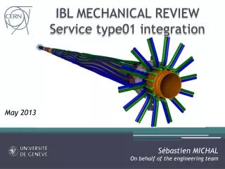
IBL MECHANICAL REVIEW May 2013
INTRODUCTION • BEAM PIPE-IPT • IPT-STAVE • IPT-IST
FINITE ELEMENT ANALYSIS • Two main thermo-mechanical analysis have been performed: • CTE mismatch between staves assemblies and IPT • PP0 area
BEAM PIPE - IPT • Beam pipe is supported in the IPT during the detector integration and the installation step. • Then it has additional supports on the IDEP at PP1 • The BP is in contact with the IPT through the BP rings made of VESPEL (ATUIBLP_0041, 0042, 0043)
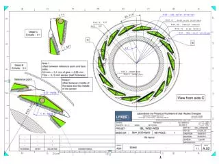
BEAM PIPE - IPT • The BP rings locations are according to drawing LHCVC1__0043 IP Area without AEROGEL
BEAM PIPE - IPT • The BP rings locations are according to drawing LHCVC1__0043 IP Area without AEROGEL IDEP support
BEAM PIPE-IPT • A critical step is the during the beam pipe bake-out: • The nominal clearance with respect to IPT is 0.7 mm • VESPEL has a CTE of • The corresponding BP ring expansion is 0.55 mm
IPT-STAVES • The holes in the EoS ring to locate the stave are within precision: • 50 µm for bonding ring positioning (ATUIBLP_0060). • 50µm for each Eos ring hole positioning (ATU-SYS-ED-0017) SIDE A SIDE C
IPT-STAVES • End-blocks of the stave are located within 50 µm precision: • This has been measured at CPPMby E.VIGEOLAS
IPT-STAVES • Our FEA stave model have been compared with previous FEA analysis (ATL-IP-EA-0007, Mauro MONTI). • At -40°C, our stave model contract by 55 µm (equivalent CTE of ) • At 50 °C, the stave will expand by 28 µm using the same CTE. Stave shrinking without end blocks in PEEK Equivalent CTE of
IPT • Single thin (5 plies) IPT: • At -40°C: extension of 17 µm (-4 e-07 .°K-1) • Bake-out: contraction of 15 µm. ESACOMP Sliding Fix
IPT-STAVES • We need at least +-150 µm space to be compatible with the end blocks holes positioning at all the detector states • We used +-500 µm in the stave support design (ATU-SYS-ED-0016) • C side has been set to be the fix point to be compatible with IPT. SIDE A SIDE C
IPT-STAVES SIDE A • Reaction forces at -40°C are around 60 N • Custom spring: • Made of SS 316 L • 10 N nominal force at 3.8 mm length • 0.5 mm diameter wire
IPT - IST Service ring Cooling line IST • The IBL package is positioned on the IST through service rings all along the IPT (ATUIBLP_0051). Type01 bundle BP ring
IPT - IST • The IPT service ring (ATUIBLP_0038) has 0.2 mm clearance with respect to IST inner diameter. • It has a 100 µm radial inner clearance for bonding • During bake-out it will expand radially by 0.02 mm Ex = Ey = 56 GPa ; Ez = 11.2 GPa Gxy = 21.3 GPa ; Gxz = Gyz = 4.7 GPa NUxy = NUyx = 0.287 ; NUxz = NUyz = 0.274 ; NUzx = NUzy = 0.055 CTEx = CTEy = 1.62 e-6 mm/mm/K CTEz = 29.2 E-6 m/mm/K Kx = Ky = 3.04 W/m-K ; Kz = 0.65 W/m-K Density = 1580 kg/m^3
IPT – IST at PP0 • The staves are located on the IST through positioning sliders fixes on the end block of the staves. Staves IP=0mm End of stave: 377 mm
IPT-IST at PP0 • 7 positionning sliders on both sides
CONCLUSION • The design of the IPT, BP rings, stave support… has been driven by finite element analysis coupled with analytical calculation and measurements (thermal and manufacturing tolerances). • Clearances of the sub-assemblies should allow a safe integration and a minimal level of stress in the IBL package during all the running conditions. THANK YOU FOR YOUR ATTENTION