CLIC Crab Cavity and Wakefields
170 likes | 328 Views
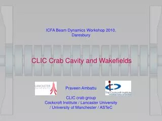
ICFA Beam Dynamics Workshop 2010, Daresbury. CLIC Crab Cavity and Wakefields. Praveen Ambattu CLIC crab group Cockcroft Institute / Lancaster University / University of Manchester / ASTeC. Crab Cavity Operation. BDS chapter of the CLIC CDR,

CLIC Crab Cavity and Wakefields
E N D
Presentation Transcript
ICFA Beam Dynamics Workshop 2010, Daresbury CLIC Crab Cavity and Wakefields Praveen Ambattu CLIC crab group Cockcroft Institute / Lancaster University / University of Manchester / ASTeC
Crab Cavity Operation BDS chapter of the CLIC CDR, http://clicr.web.cern.ch/CLICr/MainBeam/BDS/CDR/TEX/
Technology choice • High group velocity / TW cavity: • - beam-loading correction • - phase control , than SW cavity • - a = 5 mm, vgr = 2.95 % • 12 GHz cavity: • - availability of X-band Klystron • - kick per cavity • - phase tolerance • Heavily damped or moderately damped-detuned cavity: • - Transverse and longitudinal wakefield
16 cell Crab Cavity Pin=7.3 MW Pout=6 MW Vcav=2.55 MV Etr=18 MV/m Pcav=1.19 MW Pbeam=117 kW
Wakefield effects in crab cavity Bunch(es) can excite a variety of modes with different properties • Lower order mode energy spread inefficient focus • Crab / operating mode beamloading amplitude error • Same order mode vertical deflection bunches miss at IP • Higher order modes (HOMs) both monopole and dipole contributions The most dangerous in the group is the SOM which has the same frequency and kick as the operating mode but in the vertical plane.
Multibunch wakefieldin the undamped cavity, Q=6000 Single mode-Multibunch-Transverse wake: • Since the multi-bunch transverse wake field is a sum of sinusoidal oscillations, there are frequencies where the wakefield is essentially zero • This happens at harmonics of half bunch frequency (n.1GHz, n=1,3, 5..), no need of any SOM damping iff the bunches are coming at the same offset from the axis 11 GHz 13 GHz 1 MHz off 1) Fixed offset for all bunches
12 GHz 14 GHz 10 GHz 2) Fixed offset and sign alternation bunch-to-bunch 3) Random offset and random sign Damping is essential !
Fixed offset and sign alternation bunch-to-bunch , Q=30 Tolerance Random offset and random sign, Q=30
The maximum longitudinal wake occurs at the bunch harmonic • In the 12 GHz dipole cavity, the LOM occurs between 8.3 and 8.8 GHz which are far off-resonance Single mode-Multibunch-Longitudinal wake: • However, geometry modifications for damping dipole modes may shift the LOM also to resonance. So LOM damping is also essential
Damping tolerances • Transverse wake: Luminosity loss is under 2 % • Tolerance: 0.3 V/pC, for a 16 cell cavity • Longitudinal wake: Bunch energy spread is under 1e-4%, • Tolerance: 2500 V/pC for a 16 cell CC • Worst case Qs: Calculated at the frequency of maximum kick / loss factor
Crab LOM Dip3x Dip3y SOM Waveguide damping SiC load (10-j3) WR42 WR112 Dip3x SOM
w/2 eRx eRx Rx Rx Choke-mode damping The basic choke-mode cavity can’t damp the SOM, so we need to device asymmetric choke-mode dampers SiC load Elliptical cavity Slotted choke Elliptical choke SOM
Detuning to decohere SOM wake • Detuning assisted by moderate damping already in progress for the CLIC main linac • • Detuning the SOM to have a spread of frequencies by changing the equator ellipticity downstream • This allows the SOM wake to decay with Gaussian profile over a few bunch times
Uncoupled calculation V. Khan, R.M. Jones, CI / UMAN
f = 11.9942 GHz • SOM spread for detuning is limited by the group velocity of operating mode
Conclusions • Waveguide damping: • Meets the required wakefield tolerance (Q~30) • Group velocity concern • Fabrication difficulty • Choke mode cavity: • Moderate damping (Q~200) • Higher surface magnetic field • SOM detuning: • Meets required wakefield tolerance, combined with moderate damping (Q~500) • Group velocity reduction restricts achievable SOM spread • Choke-mode-detuned cavity is a good option for a possible prototype