Download

1 / 18
180 likes | 322 Views
LHC-4R crab cavity. B Hall Lancaster University / Cockcroft Institute. Cavity Design Team. G. Burt (CI- Lancs ) B. Hall (CI- Lancs ) C. Lingwood (CI- Lancs ) D. Doherty (CI- Lancs ) A. Dexter (CI- Lancs ) P. Ambattu (CI- Lancs ) C. Hill (STFC) P. McIntosh (STFC) H. Wang ( JLab )

E N D
LHC-4R crab cavity B Hall Lancaster University / Cockcroft Institute
Cavity Design Team • G. Burt (CI-Lancs) • B. Hall (CI-Lancs) • C. Lingwood (CI-Lancs) • D. Doherty (CI-Lancs) • A. Dexter (CI-Lancs) • P. Ambattu (CI-Lancs) • C. Hill (STFC) • P. McIntosh (STFC) • H. Wang (JLab) • B. Rimmer (JLab) • L. Turlington (Jlab) • Peter Stoltz (TechX) • David Smithe (TechX) • Rama Calaga (CERN) • Erk Jensen (CERN) • + several others on SM18 testing
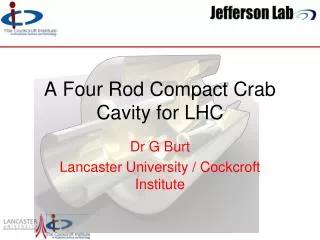
Cavity Shape • Cavity fitted LHC scenario (84 mm aperture compact transverse size) and has tolerable fields at the design gradient. • Removal of voltage variation. RT/Q=(V(a)2/wU)*(c/wa)2
Sextupole Component Due to symmetry the 4R cavity doesn’t have even components to the crab kick (monopole, quadrupole, octopole etc) The dominant error term comes from the sextupole component (m=3). The m=3 term of a simplified shape was studied. It can be seen that the m=3 term can be reduced to zero by simply modifying the angle of the focusing electrodes
Initial Problems • Initial results were not linear. • A study of the error terms showed there was still a significant perturbation from the transverse fields despite using a long thin needle. B field shift E field shift Off axis measurement On axis measurement
Corrections The transverse fields are pretty constant across the aperture hence we can do an on axis measurement and subtract it from the off axis measurement. Et Ht
Bead pull results Measurements are fairly linear but have error bars of 8%. Error bars are due to a low signal to noise ratio and a drift in the Q during measurements. The measurements are now being retaken with a higher power and checking the Q for every measurement Vz-V/m at U =1J Offset / mm
Outer can stability Although the frequency is stable with pressure the stress on the outer can when evacuated is too high. This is due to the flats on the sides of the can. The outer can is now being altered to provide more mechanical strength. Prototype has stiffening ribs
Higher Order Modes We have some TEM HOMs and a LOM. As the cavity is compact in the vertical plane most of the TM modes are at higher frequencies, and the TE modes have low shunt impedances hence has less dangerous HOMs . Dipole 3p/4 resonator Monopole 3p/4 resonator
Input and LOM Couplers Couplers have been developed for the LHC crab. Input coupler interfaces with existing LHC coupler LOM coupler reaches a low Q (100) and must handle 6 kW. Couplers are attached to the cavity body and demountable to aid cleaning.
Crab Cavity HOM Coupler Broadband Loop HOM Coupler Broadband HOM coupler needed Located opposite LOM coupler Needs to be asymmetric to couple to horizontal modes as well. LOM Coupler • Preliminary rotation of coupler
Multipactor • Multipactoron the beam pipe was found on the beam pipe at ~2MVT. • Same multipacting was seen on KEKB crab cavity. • Methods of removing the multipactor are being looked into; CI SAC meeting 29 - 31 October 2012
Nb Cavity • Rod profile was altered slightly to allow both end plates to be wire etched from single niobium block. • End plates from solid ingot • Wire EDM pre-forms from ingot • Machine all surfaces • Add beam pipes and can
Parameters after EB welding Below is design and measured (at room temperature) data before and after the final EB welding of the cavity. Courtesy of Niowave
Tests at CERN SM18 next week The cavity is currently being prepared for vertical testing mid-November at CERN in SM18.
Conclusion • Further validation of aluminium design ongoing • Need to reduce errors in the beadpull to verify field linearity to 2% level. • Initial vertical testing will take place at CERN in the week beginning Nov 19, cavity will only have basic cleaning. • The cavity will then be cleaned and baked for further testing in early 2013. • LOM and HOM coupler will be further developed, including EM design, multipactor studies, thermal management and integration into the cryostat. • Outer can needs modified to improve strength. • Need to decide how to tune the cavity and start work on a tuner.