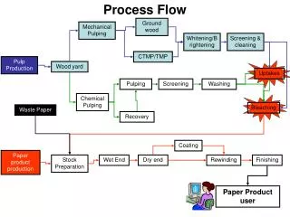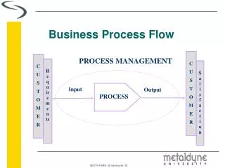
SOIMUMPs Process Flow
SOIMUMPs Process Flow. Keith Miller Foundry Process Engineer. SOIMUMPs Process. A silicon-on-insulator (SOI) wafer is used as the starting substrate: • Silicon thickness:10 ± 1 m m or 25 ± 1 µ m •Oxide thickness:1 ± 0.05 m m (10 m m) or 2 ± 0.05 m m (25 m m)

SOIMUMPs Process Flow
E N D
Presentation Transcript
SOIMUMPs Process Flow Keith Miller Foundry Process Engineer
SOIMUMPs Process • A silicon-on-insulator (SOI) wafer is used as the starting substrate:•Silicon thickness:10 ± 1 mm or 25 ± 1 µm•Oxide thickness:1 ± 0.05 mm (10 mm) or 2 ± 0.05 mm (25 mm) • •Handle wafer (Substrate) thickness:400 ± 5 mm • (2) The Silicon layer is patterned and etched down to the Oxide layer. This layer can be used for mechanical structures, resistor structures, and/or electrical routing. • (3) The Substrate can be patterned and etched from the “bottom” side to the Oxide layer. This allows for through-hole structures. • (4) A shadow-masked metal process is used to provide coarse Metal features such as bond pads, electrical routing, and optical mirror surfaces.
SOIMUMPs Process Starting Substrate - SOI Wafer FIGURE 1.2. The SOI wafers consist of a 10m(shown here) or 25m Silicon layer, a 1m or 2 mm Oxide layer, and a 400m Substrate layer. A Bottom Side Oxide layer is also initially present on the wafers
SOIMUMPs Process Silicon Doping FIGURE 1.3. A phosphosilicate glass layer (PSG) is deposited, and the wafers are annealed at 1050C for 3 hour in Argon to drive the Phosphorous dopant into the top surface of the Silicon layer. The PSG layer is subsequently removed using wet chemical etching.
SOIMUMPs Process Metal Liftoff Mask Level: PAD METAL FIGURE 1.4. The wafers are coated with negative photoresist and lithographically patterned by exposing the Photoresist with light through the first level mask (PAD METAL), and then developing it. A metal stack consisting of 20 nm chrome and 500 nm gold is deposited over the photoresist pattern by e-beam evaporation. The photoresist is then dissolved to leave behind metal in the opened areas.
SOIMUMPs Process Silicon Patterning Mask Level: SOI FIGURE 1.5. The wafers are coated with UV-sensitive photoresist and lithographically patterned by exposing the photoresist to UV light through the first level mask (SOI), and then developing it. The photoresist in exposed areas is removed, leaving behind a patterned photoresist mask for etching. Deep reactive ion etching (DRIE) is used etch the Silicon down to the Oxide layer. After etching, the photoresist is chemically stripped.
SOIMUMPs Process Substrate Patterning Mask Level: TRENCH FIGURE 1.6. A frontside protection material is applied to the top surface of the patterned Silicon layer. The bottom side of the wafers are coated with photoresist and the second level (TRENCH) is lithographically patterned. Reactive ion etching (RIE) is used to remove the Bottom Side Oxide layer. A DRIE silicon etch is subsequently used to etch completely through the Substrate layer, stopping on the Oxide layer. After the etch is completed, the photoresist is removed. A wet oxide etch process is then used to remove the Oxide layer in the regions defined by the TRENCH mask.
SOIMUMPs Process “Release” – Protection Layer and Oxide layer removal FIGURE 1.7. The frontside protection material is then stripped using a dry etch process. The remaining “exposed” Oxide layer is removed from the top surface using a vapor HF process. This allows for an electrical contact to the Substrate layer, and provides an undercut of the Oxide layer.
SOIMUMPs Process Metal Shadow Mask Fabrication Mask Level: BLANKET METAL FIGURE 1.8. A separate silicon wafer is used to fabricate a shadow mask for the Metal pattern. Standoffs are pre-fabricated into the shadow mask so that the shadow mask does not come into contact with patterned features in the Silicon layer of the SOI wafer. The shadow mask wafers are then coated with photoresist and the third level (METAL) is lithographically patterned. DRIE silicon etching is used to etch completely through the shadow mask wafer, producing through holes for the Metal to be evaporated. After the etch is completed, the photoresist is removed
SOIMUMPs Process Shadow Mask Bonding and Mirror Metal Deposition FIGURE 1.9. The shadow mask is aligned and temporarily bonded to the SOI wafer. The Mirror Metal layer, consisting of 50nm Cr + 600nm Au, is deposited through the shadow mask.
SOIMUMPs Process Shadow Mask Removal FIGURE 1.10. The shadow mask is removed, leaving a patterned Metal layer on the SOI wafer.
SOIMUMPs Structures Courtesy of University of Colorado-Boulder
SOIMUMPs Structures Courtesy of Simon-Fraser University
SOIMUMPs Published Paper • Ultra-thin Multilayer Nanomembranes For Short Wavelength Deformable Optics • Marie K. Tripp, Cari F. Herrmann, Steven M. George, and Victor M. Bright, University of Colorado, Boulder, CO USA • This work explores the creation of adaptive optics out of multilayer thin films deposited using atomic layer deposition (ALD). SOIMUMPs, ALD, flip-chip assembly, and xenon difluoride (XeF2) etching are used in the fabrication process…to our knowledge these are the first microstructures created with the ALD technique.
Beyond the Design Rules Undercut from VHF Etch Unallowable METAL Pattern Allowable METAL Pattern “Donut” Feature
Plan View Dimple Beyond the Design Rules Device layer must be removed between routing lines to be isolated Dimples in device layer to prevent stiction between beams
What can you make in SOIMUMPs?Variable Optical Attenuator (VOA)