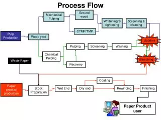
MetalMUMPs Process Flow
Learn about the MetalMUMPs process involving electroplated nickel, doped polysilicon, silicon nitride, and more for advanced semiconductor development. Follow the detailed steps from oxide deposition to trench formation.

MetalMUMPs Process Flow
E N D
Presentation Transcript
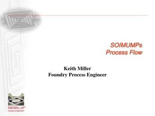
MetalMUMPsProcess Flow Stafford Johnson Advanced Development Engineering Manager
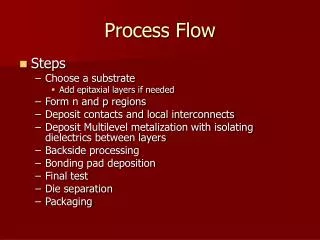
MetalMUMPs Process • (1) Electroplated nickel is used as the primary structural material and electrical interconnect layer • (2) Doped polysilicon can be used for resistors, additional mechanical structures, and/or cross-over electrical routing. • (3) Silicon nitride is used as an electrical isolation layer • (4) Deposited oxide (PSG) is used for the sacrificial layers • (5) A trench layer in the silicon substrate can be incorporated for additional thermal and electrical isolation
MetalMUMPs Process Oxide 1 Deposited FIGURE 1.2. A 2m thick oxide (Isolation Oxide) is grown on the surface of the starting n-type (100) silicon wafer. This is followed by deposition of a 0.5m thick sacrificial phosphosilicate glass (PSG) layer (Oxide 1).
MetalMUMPs Process Oxide 1 Patterned Mask Level: OXIDE1 FIGURE 1.3 The wafers are coated with UV-sensitive photoresist and lithographically patterned by exposing to UV light through the first level mask (OXIDE1), and then developing it. The photoresist in exposed areas is removed, leaving behind a patterned photoresist mask for etching. Wet chemical etching is used to remove the unwanted sacrificial PSG. After the etch, the photoresist is chemically stripped.
MetalMUMPs Process Nitride 1 and Poly Deposited Mask Level: OXIDE1 FIGURE 1.4. A 0.35m layer of silicon nitride (Nitride 1) is deposited, followed immediately by the deposition of a 0.7m layer of polysilicon (Poly).
MetalMUMPs Process Poly Patterned Mask Level: POLY FIGURE 1.5. The wafers are coated with photoresist and the second level (POLY) is lithographically patterned. Reactive ion etching (RIE) is used to remove the unwanted polysilicon. After the etch is completed, the photoresist is removed.
MetalMUMPs Process Nitride 2 Deposited FIGURE 1.6. A second 0.35m layer of silicon nitride (Nitride 2) is deposited.
MetalMUMPs Process Nitride(s) Patterned Mask Level: NITRHOLE FIGURE 1.7. The wafers are coated with photoresist and the third level (NITRHOLE) is lithographically patterned. RIE etching is performed to remove both Nitride 2 and Nitride 1 from the patterned areas. After the etch is complete, the photoresist is removed. Note: Nitride 1 will remain anywhere NITRHOLE is patterned over Poly.
MetalMUMPs Process Oxide 2 Deposited FIGURE 1.8. A second sacrificial layer (Oxide 2), 1.1m of PSG, is deposited and annealed at 1050C for 1 hour.
MetalMUMPs Process Oxide 2 Patterned and Anchor Metal Dep Mask Level: METANCH FIGURE 1.9. The wafer is coated with photoresist and the fourth mask level (METANCH) is lithographically patterned. The Oxide 2 is wet etched and a thin metal layer (Anchor Metal) consisting of 10nm Cr + 25nm Pt is deposited. A liftoff process is used to remove the photoresist and leave Anchor Metal only in the bottom of the Oxide 2 openings formed from the METANCH mask level.
MetalMUMPs Process Plating Base Dep and Plating Stencil Patterned Mask Level: METAL FIGURE 1.10 The Plating base layer, consisting of 500nm Cu + 50nm Ti is deposited. (Not shown). The wafers are coated with a thick layer of photoresist and patterned with the fifth mask level (METAL). This process forms a patterned stencil for the electroplated Metal layer.
MetalMUMPs Process Metal Plated FIGURE 1.11. Nickel is electroplated to a nominal thickness of 20m into the patterned resist stencil. A 0.5m gold layer is then immediately electroplated on top of the nickel layer. This forms the Metal layer.
MetalMUMPs Process Plating Stencil Removed FIGURE 1.12. The photoresist stencil is then chemically removed.
MetalMUMPs Process Gold Over Plating Stencil Patterned Mask Level: GOLDOVP FIGURE 1.13. The wafers are coated with photoresist and patterned with a “bloated” version of the sixth mask level (GOLDOVP) to remove Plating Base in the regions where Sidewall Metal is desired. The Plating Base is chemically removed from the unpatterned regions, and the photoresist is stripped. The wafers are coated with photoresist and patterned with an “un-bloated” version of the sixth mask level (GOLDOVP) to define a resist stencil in the regions of Metal where electroplated Sidewall Metal is desired.
MetalMUMPs Process Gold Over Plating FIGURE 1.14. A 1-3m gold layer (Sidewall Metal) is electroplated using the GOLDOVP photoresist mask as a stencil.
MetalMUMPs Process Gold Over Plating Stencil Removed FIGURE 1.15. The GOLDOVP resist stencil is stripped.
MetalMUMPs Process Plating Base and Sacrificial Oxides Removed FIGURE 1.16. Plating Base is chemically stripped in the first step of the release process. In the second step of the release process, a 49% HF solution is used to remove the PSG sacrificial layers (Oxide 1 and Oxide 2) and the Isolation Oxide layer over the trench areas.
MetalMUMPs Process Trench Formed – Silicon Etched FIGURE 1.17. In the final step of the release process, a KOH silicon etch is used to form a 25m deep trench in the silicon substrate in the areas defined by the OXIDE1 and NITRHOLE mask levels. A protective coating is applied, wafers are diced, cleane, sorted and shipped to customer.
MetalMUMPs Published Paper • Two Movable Plate Nitride Loaded MEMS Variable Capacitor • Maher Bakri- Kassem and Raafat R. MansourUniversity of Waterloo • A MEMS variable capacitor having two movable plates loaded with a Nitride layer is proposed. A trench in the silicon substrate underneath the capacitor is used to decrease the parasitic capacitance. The use of an insulation dielectric layer on the bottom plate of the MEMS capacitor increases the capacitor’s tuning range and eliminates sticktion. The tuning range was measured and found to be 280% at 1 GHz. The achievable tuning range far exceeds that of the traditional parallel plate MEMS variable capacitors. The proposed MEMS variable capacitor is built using the MetalMUMPs process.
MetalMUMPs Published Paper • Two Movable Plate Nitride Loaded MEMS Variable Capacitor • Maher Bakri- Kassem and Raafat R. MansourUniversity of Waterloo
Poly/Nickel powered gripper • Tethering 0% effective as indicated previously by JDSU • Same tether as other grippers and parts – placement along bottom only was ineffective
Parts for assembly • 100% successful tethering • 0% success parts removal with gripper • 100% successful tether break with probe and part release • No successful assembly yet
Parts for assembly • Nitride with poly rib tether was 100% effective • Poly rib • Nitride hole
MetalMUMPs Bistable Relay Contacts Disengage actuators Engage actuators
Thermal actuator • Structural layers can be electrically insulated from thermal heaters Electroplated nickel actuator Polysilicon heater
c What Can You Make in MetalMUMPs?Copper Cross Connect Switch