Download
1 / 47
490 likes | 599 Views
This presentation delves into semiconductor memory basics, RAMs, ROMs, and various memory technologies such as Flash Memories. It covers memory array structures, addressing, capacity, operations like read and write, and details of SRAM and DRAM families. The focus is on synchronous and burst SRAM organizations, cache memories, and dynamic RAM technologies with detailed illustrations and examples.

E N D
Memory and Storage Dr. Rebhi S. Baraka rbaraka@iugaza.edu Logic Design (CSCI 2301) Department of Computer Science Faculty of Information Technology The Islamic University of Gaza
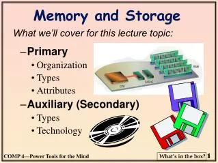
Outline • Basics of Semiconductor Memory • Random-Access Memories (RAMs) • Read-Only Memories (ROMs) • Programmable ROMs (PROMS) • Flash Memories • Memory Expansion
Basics of Semiconductor Memory • Units of binary data • Bit • Nibble (4 bits) • Byte (8 bits) • Word (1 or more bytes)
Memory Array • A single binary bit is stored in a memory cell • An organized group of cells is called a array
Memory Address and Capacity • The location of a unit of data is called the address • The capacity of a memory is the total number of data units that can be stored in a memory.
Basic Memory Operations • Write operation: puts data into a specified address in the memory
Basic Memory Operations • Read operation: takes data out of a specified address in the memory
Random-Access Memories (RAMs) • Data can be written into or read from any selected address in any sequence • When writing, old data is replaced by new ones. • When reading, data is not destroyed. • It is typically used for short-term data sotrage because it can’t retain data when power is turned of.
The RAM Family: Static RAM (SRAM) • Flip-flops are used as storage cells • Implemented in integrated circuits with several MOS transistors, or • Bipolar transistors.
The RAM Family: Static RAM (SRAM) • The cell is selected by an active level on the Select line and a data bit is written into the cell by placing it on the Data in line. • A Data bit is read by taking it off the Data out line.
The Basic SRAM Cell Array • Organized in rows and columns • Cells in a row share the same Row Select line. • Each set of Data lines go to each cell in a given column via a single line. • This line serves as both input and output (Data I/O)
Logic diagram for an asynchronous 32k x 8 SRAM. • Operation is not synchronized with a system clock. • In a read mode, 8 data bits appear on output lines. • In a write mode, 8 bits are applied to the data input lines and are stored at a selected address.
Tristate outputs and Buses • Tristate buffers in a memory allow the data lines to act as input or output lines and connect the memory to the data bus in a computer. • They have 3 output states: • HIGH (1), LOW (0), and HIGH-Z (open) • They are indicated by a small inverted triangle (See the previous slide) • A bus is a set of conductive paths that serve to interconnect two or more functional components of a system.
Memory Array • SRAM can be organized in multiple bytes (16, 64, 32 bits, etc.) • A typical 32K x 8 SRAM (see next slide) is arranged in 256 rows and 128 x 8 columns. • There are 215 =32,768 addresses and each address contains 8 bits (32kbytes). • Read • Write • Read/Write cycles
Basic read and write cycle timing for the SRAM tRC read cycle time tAQ Adress access time tEQ chip enable access time tGQ output enable access time tWC wrtie cycle time ts(A) address setup time tWD f time WE must remain low th(D) data hold time
Basic Synchronous Burst SRAM Organization • It is synchronized with the system clock • For example in a computer system, it operates with the same clock signal that operates the processor. • It uses clocked registers to synchronize all inputs with the system clock. • The address, the read/write input, the chip enable, and the input data are all latched into their respective register on an active clock pulse edge.
basic block diagram of a synchronous SRAM with burst feature.
Basic Synchronous Burst SRAM Organization • The Burst Feature • It allows the memory to read or write at up to four locations using a single address. Address burst logic
Cache Memory ذاكرة مخفية/مخبأة • One of the major applications of SRAM. • It is a relatively small, high speed memory that stores the most recently used instructions or data from the main memory which are needed by the processor. • It improves system performance • Analogy: Home refrigerator and supermarket.
Block diagram showing L1 and L2 cache memories in a computer system. Cache Memory
Dynamic RAMs (DRAMs) • Use small capacitors. • Simple, allowing very large memory arrays to be constructed on a chip at a lower cost. • Disadvantage: the capacitor can’t hold its charge without being refreshed (recharged) periodically. • Refreshing requires additional circuitry.
MOSFET Capacitor A MOS DRAM cell consisting of a single MOSFET and a capacitor
Basic Operation of a DRAM Cell Transistor acts as a switch • The R/W line, the row line, the refresh line is HIGH. • The transistor turns on, connecting the capacitor to the bit line. • The output buffer is enabled, and the stored data bit is applied to the input of the refresh buffer. HIGH
Read Only Memories (ROMs) • A ROM contains permanently or semipermanently stored data. • A ROM stores data that are used repeatedly in systems applications such as programmed instructions for system initialization (BIOS). • ROMs retain stored data when the power is off.
The ROM family. • The Mask ROM – Known also as ROM, is permanently programmed during the manufacturing process to provide widely used standard functions. • Once it is programmed it can’t be changed.
Representation of a ROM programmed as a binary-to-Gray code converter.
A 1024-bit ROM with a 256 x 4 organization based on a 32 x 32 array.
Flash Memory • Flash memory has a number of characteristics that are not found in one of the other types of memories. • high-density (High storage capacity) • Nonvolatility • In-system read and write capability • Fast operation • Cost effectiveness • A storage cell consists of a single floating-gate MOS transistor.
The storage cell in a flash memory. • The floating gate stores electrons (charge) as a result of a sufficient voltage applied to the control gate. • A 0 is stored when there is more charge • A 1 is stored when there is less or no charge.
Programming operation Storing a 0 or a 1 in a flash cell during the programming operation.
Simplified illustration of removing charge from a cell during erase.
Basic flash memory array. • When a cell in a given bit line turns on during a read operation, there is current through the bit line, which produces a voltage drop across the active load . • This voltage drop is compared to a reference voltage with a comparator and an output level indicating a 1 is produced. • If a 0 is stored, then there is no current or little current in the bit line and an opposite level is produced on the comparator output.
Memory Expansion • To increase the word length (no. of bits in each address) • To increase word capacity (no. of different addresses) • To increase both, word length and word capacity • This is accomplished by adding a no. of memory chips to the address, data and control buses.
Word Length Expansion • The number of bits in the data bus must be increased • Example: Expansion of two 65,536 x 4 ROMs into a 65,536 x 8 ROM to illustrate word-length expansion.
Example • Expand the 65,536 x 4 ROM (64K x 4) to form a 64k x 8 ROM.
SIMMs and DIMMs • Memories are supplied as: • Single In-line Memory Modules (SIMMs) • Dual In-line Memory Modules (DIMMs) • The are small circuit boards on which memory chips (ICs) are mounted with the inputs and outputs connected to an edge connector on the bottom of the board • DIMMs are generally faster and used in newer generations of machines.
These slides are based on Digital Fundamentals 9th ed. By Thomas Floyd End of the slides