MOS Memory and Storage Circuits
660 likes | 1.06k Views
MOS Memory and Storage Circuits. Class- 5 & 6. Chapter Goals. Overall memory chip organization Static memory circuits using the six-transistor cell Dynamic memory circuits Sense amplifier circuits used to read data from memory cells Learn about row and address decoders

MOS Memory and Storage Circuits
E N D
Presentation Transcript
MOS Memory and Storage Circuits Class- 5 & 6
Chapter Goals • Overall memory chip organization • Static memory circuits using the six-transistor cell • Dynamic memory circuits • Sense amplifier circuits used to read data from memory cells • Learn about row and address decoders • Read Only Memory (ROM)
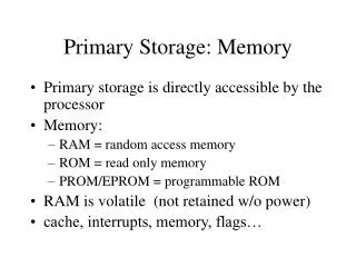
Random Access Memory • Random Access Memory (RAM) refers to memory in a digital system that has both read and write capabilities • Static RAM (SRAM) is able to store its information as long as power is applied, and it does not lose the data during a read cycle • Dynamic RAM (DRAM) uses a capacitor to temporarily store data which must be refreshed periodically to prevent information loss, and the data is lost in most DRAMs during the read cycle • SRAM takes approximately four times the silicon area of DRAM
A 256-Mbit Memory Chip • The figure shows the block structure of a 256-Mb memory • There are sets of column and row decoders that are used for memory array selection • The column decoder splits the memory into upper and lower halves • The row decoder and wordline drivers bisect each 32-Mb subarray Note that the basic building block for this memory is a 128Kb cell
A 256-Mbit Memory Chip • The memory block diagram contains 2M+N storage locations • When a bit has been selected, the set of sense amplifiers are used to read/write to the memory location • Horizontal rows are referred to as wordlines, whereas the vertical lines are called bitlines
Static Memory Cells • Inverters configured as shown in the above figure form the basic static storage building block • These cross-coupled inverters are often referred to as a latch • The circuit uses positive feedback
The 6-T Cell • With the addition of two control transistors it is possible to create the 6-T cell which stores both the true and complemented values of the data
The Read Operation of a 6-T Cell Initial state of the 6-T cell storing a “0” with the bitlines’ initial conditions assumed to VDD/2 Conditions after the WL transistors have been turned on
The Read Operation of a 6-T Cell Final read state condition of the 6-T cell
The Read Operation of a 6-T Cell Waveforms of the 6-T cell read operation: Wordline capacitive coupling effect
The Read Operation of a 6-T Cell • Reading a 6-T cell that is storing a “1” follows the same concept as before, except that the sources and drains of the WL transistors are switched • Note that the delay is approximately 20ns for this particular cell
8.2.3 The Write Operation of a 6-T Cell It can be seen that not much happens while writing a “0” into a cell that already stores a “0” Microelectronic Circuit Design, 4E McGraw-Hill
The Write Operation of a 6-T Cell While writing a “0” to a cell that is storing a “1”, the bitlines must be able to overpower the output drive of the latch inverters to force it to store the new condition
Dynamic Memory Cells • The 1-T cell uses a capacitor for its storage element (data is represented as either a presence or absence of a charge) • Due to leakage currents of MA, the data will eventually be corrupted, hence it needs to be refreshed
Data Storage in a 1-T Cell Storing a “0” Storing a “1”
The Four-Transistor (4-T) Cell • Since the 6-T SRAM provides a large signal current drive to the sense amplifier, it generally has shorter access time as compared to a DRAM • The 4-T DRAM cell is an alternative that increases access time, and automatically refreshes itself
Sense Amplifiers • Sense amplifiers are used to detect the small currents that flow through the access transistors or the small voltage differences that occur during charge sharing
Sense Amplifier • Sense amplifiers are one of the most critical circuits in the periphery of CMOS memories • Their performance strongly affects both memory access time, and overall memory power dissipation.
Sense Amplifier • As with other ICs today, CMOS memories are required • to increase speed, improve capacity and maintain low power dissipation. • These objectives are somewhat conflicting when it comes to memory sense-amp design.
Sense Amplifier • With increased memory capacity usually comes increased bit-line parasitic capacitance. • This increased bit-line capacitance in turn slows down voltage sensing and makes bit-line voltage swings energy expensive • resulting in slower more energy hungry memories
Sense Amplifier • Due to their great importance in memory performance sense amplifiers have became a very large class of circuits • Their main function is to sense or detect stored data from a read selected memory cell.
Sense Amplifier • The memory cell being read produces a current "IDATA" that • removes some of the charge(dQ) stored on the pre-charged bitlines. • Since the bit-lines are very long, and are shared by • other similar cells, the parasitic resistance "RBL" and
Sense Amplifier • capacitance "CBL" are large. Thus, the resulting bit-line voltage swing (dVBL) caused by the removal of "dQ" from the bitline is very small dVBL=dQ/CBL • Sense amplifiers are used to translate this small voltage signal to a full logic signal that can be further used by digital logic.
Sense Amplifier • The need for increased memory capacity, higher speed, and • lower power consumption has defined a new operating environment for future sense amplifiers
Sense Amplifier • Decreasing memory-cell area to integrate more memory on a • single chip reduces the current IDATA that is driving the now heavily loaded bit-line. This coupled with increased CBL causes an even smaller voltage swing on the bit-line.
Sense Amplifier • Decreased supply voltage results in smaller noise margins • which in turn affect sense amplifier reliability
Sense-Amplifier Based Registers • fundamental approaches towards building edge-triggered registers: the master-slave concept and • the glitch technique • another technique that uses a sense amplifier structure to implement an edge-triggered register
Sense Amplifier • Voltage Sense Amplifiers • Current-Sensing amplifiers
Sense Amplifier • SRAM sense amplifiers based on voltage sensing are • widely used and established. However, this principle • becomes slow for low supply voltages and large • memories, since the cell current discharges the bit lines until a considerable voltage swing is reached
Sense Amplifier • . Current sensing that uses the cell current directly as a signal keeps the bit line voltages nearly constant and • results in fast read operation. This requires a sense amplifier with low input resistance for good impedance matching. • The most simple circuit to provide a low input resistance is the common gate stage
Sense Amplifier • structure for current sensing has been mentioned. • The new concept uses the common gate transistor also as a multiplexer. For this reason the gate voltage is controlled by the select signal SEL of the • bit line multiplexer (MUX).
Current Sense Amplifier • A main advantage of current sensing principles • compared to voltage sensing is their superior behavior • for low voltage operation where the driving cell current • becomes very small.
Sense Amplifier • Replacement a current-sensing amplifier has been introduced, and its ability to overcome problems associated with voltage sensing may further examined.
A Sense Amplifier for the 6-T Cell • MPC is the precharge transistor whose main purpose is to force the latch to operate at the unstable point previously mentioned
A Sense Amplifier for the 1-T Cell • The same sense amplifier used in the 6-T cell can be used for the 1-T cell in manner shown in the figure
The Boosted Wordline Circuit • Obviously it is desired to have a fast access in many DRAM applications. • By driving the wordline to a higher voltage (referred to as a boosted wordline), say 5V instead of 3V, it is possible to increase the amount of current supplied to the storage capacitors
Clocked CMOS Sense Amplifiers • The sense amplifier can definitely be a major source of power dissipation, but by using a clocking scheme, it is possible to reduce the power dissipated, Dummy Cell (DC), Precharge (PC), Latch clock (LC)
Address Decoders • The following figures are examples of commonly used decoders for row and column address decoding NMOS NOR Decoder NMOS NAND Decoder
Address Decoders Complete 3-bit NAND decoder
Read-Only Memory (ROM) • ROM is often needed in digital systems such as: • Holding the instruction set for a microprocessor • Firmware • Calculator plug-in modules
Read-Only Memory (ROM) • The basic structure of the NMOS static ROM is shown in the figure • The existence of an NMOS transistor means a “0” is stored at that address otherwise a “1” is stored • Power dissipation is large
Read-Only Memory (ROM) • The domino CMOS ROM is one technique used to lower the amount of power dissipation
Read-Only Memory (ROM) • Another ROM option is the NAND array ROM which can be directly used with a NAND decoder
Read-Only Memory (ROM) • The main problem with these previous ROMs is that they must be designed at the mask level, meaning that it is not a versatile product. • To solve this problem, the programmable ROM (PROM) was introduced • The standard PROM cannot be erased, so the erasable ROM (EPROM), and later, electrically erasable ROM (EEPROM) were introduced • High density flash memories allow for electrical erasure and reprogramming of memory cells
RS Flip-Flop • The reset-set (RS) flip-flop can be easily realized by using either two cross-coupled NOR or NAND gates • The RSFF has the following truth tables NOR RSFF NAND RSFF