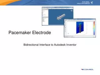
Pacemaker Electrode
Pacemaker Electrode. Bidirectional Interface to Autodesk Inventor. Capabilities of the Bidirectional Interface. Associatively transfer geometry from the open active document, either part or assembly, in Autodesk Inventor to COMSOL Multiphysics.

Pacemaker Electrode
E N D
Presentation Transcript
Pacemaker Electrode Bidirectional Interface to Autodesk Inventor
Capabilities of the Bidirectional Interface • Associatively transfer geometry from the open active document, either part or assembly, in Autodesk Inventor to COMSOL Multiphysics. • Update geometry parameters in the open active document in Autodesk Inventor. • Set up an automatic parameter sweep for multiple geometry parameters. Take advantage of distributed memory systems, such as Windows and Linux clusters.
Model Definition Boundaries with applied positive potential. • The geometry represents a pacemaker electrode. • This model studies the heating effect of the current flowing through the surrounding tissue. Grounded boundaries. Cylinder representing the surrounding tissue.
Workflow • Open the CAD file in Autodesk Inventor. • Transfer the geometry with the interface. • Set up and solve the model in COMSOL Multiphysics • Draw additional geometry • Define integration variable to evaluate the resistive heat • Assign material properties • Define boundary settings • Create a mesh • Solve the model. • Study the effect of geometry design parameters on the solution either by manual or automatic parametric sweep.
The bidirectional interface always transfers the geometry in the open active document in Autodesk Inventor.
In the COMSOL Multiphysics Model Navigator select the Conductive Media DC application mode.
In the COMSOL Multiphysics GUI select File>Inventor Connection>Initialize to transfer the geometry and initialize the connection between COMSOL Multiphysics and Autodesk Inventor.
When the transfer is ready the geometry appears in the COMSOL Multiphysics GUI.
Use the drawing tools in COMSOL Multiphysics to create the geometry for the surrounding tissue.
To evaluate the total resistive heat in the tissue define a variable in the Subdomain Integration Variables dialog box.
Set the material properties in the Subdomain Settings dialog box.
Define the electric potential and grounded boundaries in the Boundary Settings dialog box.
Click the Solve button to solve the model. Slice plot of the electric potential in the tissue surrounding the electrode.
Use the Plot Parameters dialog box to plot the resistive heating in the tissue.
Parametric Study • Study the effect of design parameters on the resistive heating. Position of grounded region. Size of region where positive potential is applied.
Update of Geometry Parameters from the COMSOL Multiphysics GUI • Use the automatically generated geometry parameters in Autodesk Inventor or define your own parameters. • Define corresponding constants in COMSOL Multiphysics to which you can assign new values. • Update the geometry from the COMSOL Multiphysics GUI. • Geometry parameters and the geometry in the Autodesk Inventor document are updated and sent back to COMSOL Multiphysics • Subdomain, boundary and mesh settings are associative and retained in the updated model. • Solve the model again.
To find out the name of parameters in the Autodesk Inventor GUI edit a sketch. In the sketch, double click on a dimension to edit it. The parameter d12 is the radius of the sphere which we would like to update through the interface.
Link the radius parameter to d12 by typing radius in the Equation field of d12.
The other design parameter, the position of the grounded region is d14, which is also found in Sketch1. Control the value of d14 directly through the bidirectional interface.
In the COMSOL Multiphysics GUI select Constants from the Options menu.
Enter the constants radius and d14 and their new values 1 and 12, respectively. During update of the geometry these constants will be transfered to Autodesk Inventor to update the corresponding parameters.
Select File>Inventor Connection>Update to transfer the constants to Autodesk Inventor and to transfer back the updated geometry to COMSOL Multiphysics.
When the transfer is ready the updated geometry appears in the COMSOL Multiphysics GUI.
In the Autodesk Inventor GUI the parameters and the geometry have been updated.
Click the Solve button in the COMSOL Multiphyiscs GUI to obtain the new solution.
Parametric Sweep • Automatically solve the model for a range of geometry parameters. • Obtain a log-file containing design parameters and selected global variables evaluated for each solved model. • Optionally save each solved model as an .mph file.
Select File>Inventor Connection>Geometric Parametric Sweep to set up and automatically solve the model for a range of geometry parameters.
Enter a name for the log file and list the variables to be evaluated. Enter a list of geometry parameters, and a range of values Click Solve to start the sweep. You can also select to save each solved model file separately.