Download
1 / 42
420 likes | 568 Views
Delve into the world of radar technology for remote sensing, exploring active sensors, radar frequencies, Synthetic Aperture Radar (SAR), backscatter phenomena, and Earth-observing space-based SAR systems. Learn about resolution, polarization, and SAR data processing methods.

E N D
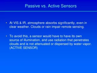
At VIS & IR, atmosphere absorbs significantly, even in clear weather. Clouds or rain impair remote sensing. To avoid this, a sensor would have to have its own source of illumination, and use radiation that penetrates clouds and is not attenuated or dispersed by water vapor. (ACTIVE SENSOR) Passive vs. Active Sensors
Radar: radio detection and ranging System: radar works at wavelengths between 0.1-30 cm. (microwave) (note: frequency is preferred unit of measurement because it is constant in different media, and wavelength is not) C = = (3*108 m s-1)/ [cm] = 30/( [GHz]) R A D A R
Radar frequencies designated by random- letter code to avoid mention of wavelength or frequencies during classified research (Ka, K, Ku, X, C, S, L, P) Early airborne radars: Ka; today many are X-band Synthetic Aperture Radar (SAR)
Shorter wavelenths provide higher spatial (azimuth) resolution but less “all weather” penetration
Range or Look direction Azimuth direction is flight direction
Different surfaces cause: Strong returns: Features facing radar Targets with corners Weak returns: water: specular reflector sloping features facing away RADAR
A. RADAR IMAGE. Aircraft radar image of Weiss Lake and vicinity, northeast Alabama
B. LOCATION MAP. Aircraft radar image of Weiss Lake and vicinity, northeast Alabama.
Radar illumination and shadows at different depression angles
Airborne/space systems: Real - Aperture (“brute-force”) Radar: (make antenna as big as possible) Side looking Airborne Radar (SLAR) Synthetic Aperture Radar (SAR) SAR technology declassified in 1970 and first large-scale projects were to map rain forests of Central and South America. Synthetic Aperture Radar (SAR)
Spatial resolution depends on size of optics (aperture) relative to the wavelength of radiation received (larger size antenna or lens yields better spatial resolution) Range resolution depends on depression angle and pulse length Azimuth resolution depends on antenna length and wavelength of pulses (is better in near range) Resolution (brute-force Radar)
SAR: uses a small antenna to transmit a broad beam uses doppler info. to synthesize azimuth resolution Spatial resolution (azimuth) is constant in the range direction (in real-aperture radars, azimuth resolution decreases (is “coarser” or worse) in the far range) Synthetic Aperture Radar (SAR)
Backscatter = radar cross section units of area (such as square meters). The backscatter is often related to the size of an object, with objects approximately the size of the wavelength (or larger) appearing bright (i.e. rough) and objects smaller than the wavelength appearing dark (i.e. smooth). A measure of backscatter is the normalized radar cross section, which independent of the image resolution or pixel size. Normalized radar cross section (sigma.) is measured in decibels (d). Typical values of sigma. for natural surfaces range from +5d (very bright) to -40d (very dark). Synthetic Aperture Radar (SAR)
Backscatter will also vary depending on polarization. Some SARs can transmit pulses in either horizontal (H) or vertical (V) polarization and receive in either H or V, with the resultant combinations of HH (Horizontal transmit, Horizontal receive), VV, HV or VH. Some SARs can measure the phase of the incoming pulse (one wavelength = 2pi in phase) and therefore measure the phase difference (in degrees) in the return of the HH and VV signals. This difference can be thought of as a difference in the roundtrip times of HH and VV signals and is frequently the result of structural characteristics of the scatterers. These SARs can also measure the correlation coefficient for the HH and VV returns, which can be considered as a measure of how alike (between /not alike and 1/alike) the HH and VV scatterers are. Synthetic Aperture Radar (SAR)
Earth-observing Space-based SAR Systems: SeaSat (1978) SIR (Shuttle Imaging Radar) SIR-A (1981) SIR-B (1984) SIR-C / X-SAR (1994) SRTM (2000) JERS-1 (Japan) ERS-1 / 2 (Europe) RADARSAT (Canada) MIR / Priroda / Almaz (Russia) Envisat Future: TOPSAR (?) LightSAR (?) / Others Synthetic Aperture Radar (SAR)
Data rate: (bits/sample)(samples/area)(area/time) bits/sample = 8 bits/sample area/sample = 25m x 6.25 m = 156 m2 area/time = swath width x radar velocity = 100 km x 7 km/s = 0.7x10⁹ m2/s Data rate ~ 36 Mbit/s = 8Mbyte/s Synthetic Aperture Radar (SAR)
SAR Processing: Deformations: Image layover (not much of an issue in oceanography): curvature of transmitted radar pulse causes top of a vertical target to reflect energy in advanced of its base. Slant-range vs. ground-range Focused SARs (through data processing) can correct these effects Synthetic Aperture Radar (SAR)
Synthetic Aperture Radar (SAR) Image “layover” or “foreshortening”
Layover of topographic features on a radar image of the Grapevine Mountains on the east side of Death Valley, California. Images courtesy G.C. Schaber, U.S. Geological Survey
Synthetic Aperture Radar (SAR) Illumination direction effects
Deformations: Doppler errors: Instrument Earth rotation (can be compensated for) Speckle: Graininess due to coherent superposition of radar reflections from different areas within one pixel Rain: tends to dampen waves at surface and therefore will produce low reflectivity (dark regions in SAR images) Target Motion: Main effects are: target is displaced to new position in image target has new focal point (in front or behind stationary targets) depth of focus is altered If target moves too fast (aster than apparent velocity of stationary target), it will no be imaged Targets moving toward radar will be displaced in the direction of radar motion, those moving away are displaced in opposite direction Synthetic Aperture Radar (SAR)
SAR applications: Land Geology Vegetation mapping Soil moisture Reconnaisance Interferometry: Surface distortions (Earth quakes, volcanism) DEM / Topography Ocean: Map reflectivity over areas 50-100 km per side \, with 10-40 m resolution Internal waves Surface wave spectra Fronts Eddies Ice mapping Glacier/iceberg detect. Shipping reconn. Surface slicks wind speed Issues: data volumes, target motion, navigation, deformations Synthetic Aperture Radar (SAR)
Oil spill - North Sea Image Description A long oil slick discovered on the SAR image of the 17th September 1992 in the North Sea, outside Jaeren. It has been confirmed by the monitoring aircraft and by commercial helicopters. The area of the slick was 2 km and its thickness 0.003 mm, the amount of oil was estimated at 200 liters. The windspeed was reported to be 2 m/s.
The Prestige incident (Nov 2002-April 2003) http://earth.esa.int/ew/oil_slicks/galicia_sp_02/ Hurricane Katrina (Aug/Sep 2005) http://www.skytruth.com/ Oil spill detection with SAR