Download
1 / 28
280 likes | 437 Views
The 1st Result of Global Commissioning of the ATALS Endcap Muon Trigger System in ATLAS Cavern. ~ Contents ~ ATLAS Level1 Trigger Endcap muon trigger system Global Commissioning Run (Milestone-3 run) Results Summary. Takuya SUGIMOTO (Nagoya University) On behalf of TGC Group. Introduction.

E N D
The 1st Result of Global Commissioningof the ATALS Endcap Muon Trigger Systemin ATLAS Cavern • ~ Contents ~ • ATLAS Level1 Trigger • Endcap muon trigger system • Global Commissioning Run (Milestone-3 run) • Results • Summary Takuya SUGIMOTO (Nagoya University) On behalf of TGC Group
LHC-ATLAS Experiment Barrel muon chamber EM calorimeter Inner tracker 7TeV proton 7TeV proton Solenoid magnet 25m Barrel toroidal magnet 45m Endcap muon chamber Hadron calorimeter Endcap toroidal magnet T. Sugimoto (Nagoya-U)
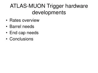
Characteristics Rate reduction: 1GHz 100kHz Decision time: < 2.5ms Only raw electronic signals are used Muon Trigger System Endcap (1.05<|h|<2.4) Thin Gap Chamber (TGC) Barrel (|h|<1.05) Resistive Plate Chamber (RPC) Air-core super-conducting toroidal magnet (Endcap and Barrel) Barrel Toroidal Magnet Endcap Toroidal Magnet ATLAS Level1 Trigger Calorimeter Trigger Muon Trigger Barrel Muon Trigger (RPC based) Endcap Muon Trigger (TGC based) Front-end Preprocessor Jet/ Energy-sum Processor Cluster Processor Muon Trigger/CTP Interface Central Trigger Processor TTC TGC1 Big Wheel T. Sugimoto (Nagoya-U)
Thin Gap Chamber • Structure • Similar to MWPC • Wire : 50mm gold-plated Tungsten • Anode-Cathode Gap : 1.4mm • Wire-Wire Gap : 1.8mm • 2-dimentional readout (wire, strip) • Cathode plane: carbon (~MW/cm2) • Trapezoidal shape (~2m2) • Operation condition • Gas : CO2 + n-C5H12 (55:45) • High Voltage : +2.9kV • Operation Mode : Limited Proportional • Gas Gain : ~106 • Production and Inspection • In total 3600 chambers were produced in Japan (KEK), Israel (Weizmann) and China (1999 – 2006) T. Sugimoto (Nagoya-U)
Endcap Muon Trigger System • Big Wheel • Triplet (TGC1), middle doublet (TGC2) and pivot doublet (TGC3) • Each BW consists of 12 sectors 72 sectors are required. • Measurement items • muon hit position • Rough Pt momentum trigger if Pt > 6GeV 1. Connect the IP and hit point on TGC3 Infinite momentum track 2. Hit signal on TGC1&2 is found in window1&2. Pt > 6GeV 3. Pt information is divided into 6 Pt threshold using LUT. 4. Pt threshold and hit position MUCTPI T. Sugimoto (Nagoya-U)
TGC Assembly at CERN 1/12 sector Assembly (Oct. 2005 ~ Aug. 2007) (detail T. Kubota's poster) TGC Big Wheel Assembly (Jul. 2006~) Sector Transportation 5 wheels assembled T. Sugimoto (Nagoya-U)
Installation of Electronics Modules 22m TGC Big Wheel Optical Fiber (~100m) Counting Room (USA15) + CCI, SL, ROD, TTC + VME Crate, SBC + Optical PP 19” Mini-Rack + HSC, SSW, HPT (CTM) + LV, HV + Optical PP On-Detector Module + SPP, PP, SLB + DCS modules T. Sugimoto (Nagoya-U)
ASICs for TGC Electronics TGC1 TGC2 TGC3 VME64 Crates (USA15) HSC(VME) (Big Wheel edge) PS-Board on TGC chambers ASD Trigger crate SLB ASIC PP delay BCID H-Pt wire 3/4 Coin. Readout Sector Logic H-Pt PP JRC delay BCID H-Pt strip Readout crate DCS-PS Doublets ROD ASD H-Pt Board PP SLB ASIC delay BCID SSW 2/3 Coin. Readout Control crate ASD PP JRC delay BCID SLB CCI HSC DCS-PS Triplet PP TTCvi Service PP CAN DCS LCS TTC signal fanout to PS-Boards ASD card TTCrq PS Board T. Sugimoto (Nagoya-U)
conv Antifuse FPGAs for TGC Electronics TGC1 TGC2 TGC3 VME64 Crates (USA15) HSC(VME) (Big Wheel edge) PS-Board on TGC chambers ASD Trigger crate SLB ASIC PP VME delay BCID H-Pt wire 3/4 Coin. Readout Sector Logic JRC PP JRC delay BCID H-Pt strip Readout crate DCS-PS Doublets H-Pt Board ROD SSWRX ASD PP SLB ASIC delay BCID SSW 2/3 Coin. Readout VME PS Board Control crate PP JRC delay BCID CCI HSC VME DCS-PS Triplet TTCvi Service PP CAN SSWTX TTC signal fanout to PS-Boards HSC Board TTCrq SSW Board T. Sugimoto (Nagoya-U)
<Main purpose of Global Commissioning> Provide Trigger Signal to whole sub-detectors mainly MDT EndCap Read out TGC data via ROD-ROS link Join TGC segmentto the ATLAS central DAQ system TGC for Global Commissioning Run TGC1 MDT Chamber condition + Gas: CO2 100% + HV: 2.8kV + Eff: ~20% TGC1 Sector 09 T. Sugimoto (Nagoya-U)
TGC Electronics On TGC chambers Big Wheel edge Counting Room TGC1 TGC2 TGC3 PS-Board HSC(VME) crate VME64 crates ASD Trigger crate SLB ASIC PP R Trigger delay BCID H-Pt wire 3/4 Coin. Readout Sector Logic MUCTPI f PP JRC delay BCID H-Pt strip Readout crate DCS-PS Doublets Readout ROD ROB ASD PP SLB ASIC delay BCID SSW 2/3 Coin. Readout Control crate PP JRC delay BCID Control CCI HSC DCS-PS Triplet TTC TTCvi CTP Service PP CAN DCS LCS TTC signal fanout to PS-Boards TTCrq T. Sugimoto (Nagoya-U)
Setup for Global Commissioning On TGC chambers Big Wheel edge Counting Room TGC1 HSC(VME) crate VME64 crates Trigger crate Specially designed modules instead of HPT Trigger CTM Sector Logic MUCTPI Readout crate Readout 1-station coincidence ROD ROB ASD PP SLB ASIC delay BCID SSW 2/3 Coin. Readout Control crate PP JRC delay BCID Control CCI HSC m DCS-PS Triplet TTC TTCvi CTP Service PP CAN DCS LCS TTCrq T. Sugimoto (Nagoya-U)
Commissioning Trigger Module (CTM) • Functionality • 11 FPGAs • XILINX SPARTAN XC2S50E • 10 are used for Rx (LVDS). • Take all OR , mask any inputs • 1 is used for Tx (NIM). • CPLD: VME control. • XILINX XC2C256P • Purpose • Trigger output is asserted by all trigger matrices on SLB ASIC. • Usable to give 1-station trigger signal It is impossible for HPT • Various trigger pattern by input mask • wire only / strip only / wire & strip Input From PS boards (LVDS) VME Rx Tx Output To SL (NIM) T. Sugimoto (Nagoya-U)
Local Trigger Path On TGC chambers Big Wheel edge Counting Room TGC1 No logic No LUT Fixed Pt HSC(VME) crate VME64 crates Trigger crate CTM Sector Logic Readout crate 1-station coincidence L1A ROD ASD PP SLB ASIC delay BCID SSW 2/3 Coin. Readout Control crate PP JRC delay BCID CCI HSC DCS-PS Triplet TTCvi Service PP CAN TTCrq T. Sugimoto (Nagoya-U)
Vth vs Trigger Rate • half sector • 2/3 coincidence (wire) • Gas: CO2 100% • HV: 2.8kV • good separation between S/N with threshold of 100mV • finally, we got stable 8Hz of trigger fromFULL TGC1 sector9 and fed them to CTP ( they found it in their system ) T. Sugimoto (Nagoya-U)
CCI-HSC Link (optical) Control Path On TGC chambers Big Wheel edge Counting Room TGC1 HSC(VME) crate VME64 crates • CCI-HSC link • Optical communication module • CCI: VME Slave • HSC: VME Master • JRC (Jtag Route Controller) Trigger crate CTM Sector Logic Readout crate Standard VME Protocol ROD ASD PP SLB ASIC delay BCID SSW 2/3 Coin. Readout Control crate JTAG PP JRC delay BCID CCI HSC DCS-PS I2C Triplet TTCvi Service PP CAN DCS LCS Control SBC TTC signal fanout to PS-Boards TTCrq Reset T. Sugimoto (Nagoya-U)
Global Trigger Path On TGC chambers Big Wheel edge Counting Room TGC1 No logic No LUT Fixed Pt HSC(VME) crate VME64 crates Trigger crate CTM Sector Logic MUCTPI Readout crate ROD ASD CTP PP SLB ASIC delay BCID SSW 2/3 Coin. Readout Control crate PP JRC delay BCID L1A Clock CCI HSC DCS-PS Triplet TTCvi Service PP CAN L1A Clock TTC signal fanout to PS-Boards MDT-EC TTCrq T. Sugimoto (Nagoya-U)
TDC Distribution of MDT RPC TGC+MDT Dt = tTGC – tRPC – tTOF ~ 130nsec Provide Trigger to whole ATLAS system!! T. Sugimoto (Nagoya-U)
Track Reconstruction by MDT T. Sugimoto (Nagoya-U)
Readout Path On TGC chambers Big Wheel edge Counting Room TGC1 HSC(VME) crate VME64 crates Trigger crate • Local readout system • Special dump module for SSW data (spy mode) • Used for quick check w/o ROD CTM Sector Logic Readout crate Readout ROD ROB ASD PP SLB ASIC delay BCID SSW 2/3 Coin. Readout Local Readout Control crate PP JRC delay BCID CCI HSC DCS-PS Triplet CTP TTCvi Service PP CAN TTC signal fanout to PS-Boards TTCrq L1A, Clock T. Sugimoto (Nagoya-U)
Measurement of L1A latency Test Pulse with Track Pattern L1A Signal PP SSW Local Readout system L1Buffer CTM SL 2/3 count SLB ASIC CTP + TTC MUCTPI layer1 ch L1A Latency is 76 clocks = 1.90 msec (< 2.5 msec) layer2 Estimation: 75clk (by O.Sasaki, 2004) layer3 T. Sugimoto (Nagoya-U)
Hit Profile for cosmic-ray test Wire Hit Profile of Endcap Region • 2/3 coincidence (wire) • Vth = 100mV • Gas: CO2 100% • HV: 2.8kV T5 T6 T7 T8 layer1 layer2 layer3 ch ( = R) • first data taken by local Readout path • chambers are working fine • We are triggering cosmic-muons • trigger & readout path are working fine !! Strip Hit Profile of Endcap Region T5 T6 T7 T8 layer1 layer2 T. Sugimoto (Nagoya-U)
Summary • Provide trigger signal to ATLAS global DAQ system • TGC1 sector was used. • 1station coincidence CTM board instead of HPT board • Cosmic ray muons are triggered successfully in ATLAS cavern. • Trigger & Readout path are working fine. • Measured latency is consistent with estimated value (1.9msec) • MDT reconstructed the cosmic muon trajectory using TGC trigger. • Plan toward Physics Run • Extend number of operational sectors • 3station coincidence run done during the latest commissioning run • Timing Adjustment between stations. • Beam halo & single beam run Full system operation should be tested before starting physics run!! T. Sugimoto (Nagoya-U)
Trigger Logic T. Sugimoto (Nagoya-U)
Multiplicity Distribution (events triggered by TGC) Wire + Strip wire Strip Wire + Strip ( log ) running with CO2 reasonable T. Sugimoto (Nagoya-U)