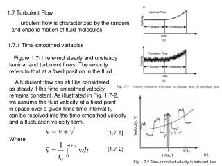
Download
1 / 22
220 likes | 383 Views
Hydraulic Fracture along Glacier Beds by Turbulent Flow of Meltwater James R. Rice (1, 2) and Victor C. Tsai (1) 1. Department of Earth and Planetary Sciences 2. School of Engineering and Applied Sciences Harvard University.

E N D
Hydraulic Fracture along Glacier Beds by Turbulent Flow of Meltwater James R. Rice(1, 2) and Victor C. Tsai(1) 1. Department of Earth and Planetary Sciences 2. School of Engineering and Applied Sciences Harvard University
Motivated by Das, Joughin, Behn, Howat, King, Lizarralde & Bhatia (Sci. '08), Fracture Propagation to the Base of the Greenland Ice Sheet During Supraglacial Lake Drainage U
Supra-glacial meltwater lake began filling July 2006 • Maximum ~0:00 29 July 2006, 0.44 km3, 5.6 km2 • Level slowly/steadily falls, 15 mm/hr • Rapid from 16:00-17:30, max 12 m/hr (Q > 104 m3/s), avg Q ~ 8700 m3/s
Interpretation • Initially: Crack/moulin system gradually propagates to bed by Weertman gravitational instability. • Middle Stage: Hydraulic cracking and flooding along bed by over-pressure, p > o . • End: Fracture closes, subglacial water layer drains.
Other interpretations: • Lake at an Ice Dam , Onset of Sub-Glacial Flooding (Jökulhlaup) • Over-Pressurized Sub-Glacial Lake, Onset of a Drainage Episode U
Modifying solution by: Desroches, Detournay, Lenoach, Papanastasiou, Pearson, Thiercelin and Cheng, The crack tip region in hydraulic fracturing, Proc. R. Soc. Lond., 1994 p Negligible fracture toughness fluid particle velocity = U Results valid asymptotically(R 0), or for all Rassuming steady state solution in infinite solid. Conservation of fluid volume: fluid particle velocity = crack propagation speed = U
Modifying solution by: Desroches, Detournay, Lenoach, Papanastasiou, Pearson, Thiercelin and Cheng, The crack tip region in hydraulic fracturing, Proc. R. Soc. Lond., 1994 p Negligible fracture toughness fluid particle velocity = U Elasticity theory: Relates w(R) to p(R) Wall roughness Turbulent fluid flow with Manning resistance:
Additional elastic stress field determined: Fix w(x), wipe out boundary tractions, hope change in p is nearly uniform (it was) Results shown for rbound ~ H ~ L
Making contact with the observations [Das et al., '08] of surface-lake drainage driving hydraulic fracture near a margin of the Greenland Ice Sheet, and others: For E' = 6.8 GPa, r = 103 kg/m3, pinlet–so = 0.86 MPa , k = 10 mm, L = 1 km: •U = 7.8 m/s , wavg = 0.61 m. • If half of pinlet–so is lost on way to base, U = 3.5 m/s , wavg = 0.31 m. • If L is reduced by a tenth, L = 0.1 km, U = 5.3 m/s , wavg = 0.06 m. • Young's modulus E = 6.2 GPa at –5ºC [Jellinek et al., '55] and Poisson's ratio n = 0.3 [Vaughan, '95], gives E' = 6.8 GPa. • Fluid density r = 1000 kg/m3. • Ice thickness H = 980 m [Das et al., '08], so if no head loss along water column to glacial surface, pinlet–so = 0.86 MPa. • Dependence of U on channel wall roughness k is weak (power law exponent = 1/6); estimate k = 10 mm, which is consistent with nManning ~ 0.018. •Fracture length L = 1 km
Greenland lake drainage comparisons: • Assuming L = 1 km, and effective width in orthogonal direction = 1 km, predicted Q = U L wx = 0 = 8800 m3/s Comparable to measured average rapid lake drainage rate Q = 8700 m3/s. • Predicted crack volume V = wavg L2 ~ 6.1 x 10⁵ m3. Much less than lake volume of ~ 4.4 x 10⁷ m3. Not resolved. GPS shows large horizontal displacement, maybe consistent with large storage on moulin system. Subglacial channels may also contribute.
Adachi and Detournay, Self-similar solution of a plane-strain fracture driven by a power-law fluid, Int. J. Numer. Anal. Meth. Geomech., 2002 L(t) ~ ta , w(x,t) ~ tbF(x / L(t)) , p(x,t) – po =G(x / L(t)) We want n = 1/3, but U2 not Un.
Abstract: The problem of hydraulic fracture has been studied extensively, with focus ranging from enhanced hydrocarbon flow to boreholes, to water-driven glacial cracking, to magma eruption through Earth's crust. Although some of this work has addressed fast-flowing fracture, the work applied to glaciers has, so far, focused either on static or relatively long timescale conditions. However, glaciological observations suggest that the fluid-induced fracture process may occur quickly, possibly driven by turbulently flowing water during crack growth. Here, we take the approximation of a fully turbulent flow into an elastic ice medium with small fracture toughness to derive an approximate expression for the crack-tip speed. We accomplish this by first showing that a Manning channel model for wall resistance to turbulent flow leads to the same mathematical structure as for resistance to laminar flow of a power-law viscous fluid. We then make use of the asymptotic crack solution for that case by Desroches et al. [Proc. R. Soc. Lond. A, 1994], and finally estimate the pressure scale appropriate for a finite crack. Comparison of this estimated solution with an exact self-similar solution of Adachi and Detournay [Int. J. Numer. Anal. Meth. Geomech., 2002] validates the approximation. To apply this model, we use parameter values thought appropriate for a basal crack driven by the rapid drainage of a surface meltwater lake near the margin of the Greenland Ice Sheet (Das et al. [Science, 2008]). Thus, we take a maximum excess crack inlet pressure of 0.9 MPa, corresponding to neglect of any hydraulic head loss in flow from the glacier surface to crack entry at the bed, a horizontal basal crack length of 1 km, and a wall roughness scale for flow resistance of 10 mm, and hence estimate a crack-tip speed of about 8 m/s. Loss of ten percent of the surface head on descent to the bed would reduce that speed by slightly more than ten percent. Making various plate theory and linear elastic fracture mechanics approximations perhaps relevant to this setting, we additionally model both vertical and horizontal surface displacements and find rough agreement with the meter-scale displacements observed through GPS by Das et al. [Science, 2008].