Download
1 / 34
340 likes | 736 Views
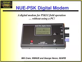
NUE-PSK Digital Modem. A digital modem for PSK31 field operation … without using a PC!. Milt Cram, W8NUE and George Heron, N2APB. NUE-PSK Digital Modem.

E N D
NUE-PSK Digital Modem A digital modem for PSK31 field operation … without using a PC! Milt Cram, W8NUE and George Heron, N2APB
NUE-PSK Digital Modem NUE-PSK is a standalone, battery-operated digital modem using a Microchip dsPIC microcontroller. The project uses a backlightable graphic LCD to display transmit and receive text data, band spectrum and a tuning indicator. Using GPL open source software, the modem can be inexpensively homebrewed. When coupled with an SSB-capable transceiver, you too can have an effective portable PSK31 station.
Agenda • PSK31 Basics • Design Approach • Hardware Design • Software Design • Demonstration Video • Kit Availability
PSK31 Basics • Designed by Peter G3PLX, • Better than SLOWBPSK, an idea and implementation of SP9VRC, • Based on the RTTY mode of operation, • Useful for live keyboard to keyboard QSO, • Works at 31.25 baud, • Uses varicode character coding that gives 50wpm, • Easy to use and monitor, • Gives very good copy under low Eb/No numbers and is thus suitable for QRP, • Instead of using FSK or on/off keying uses BPSK or QPSK with a Viterbi decoder, • Available free for many platforms, including Windows with SoundBlaster type Soundcard, • Uses advanced DSP and narrow band (31 Hz!!) techniques.
PSK31 Basics - Transmit TX – Pair of tones separated by 31.25 Hz … classic 2-tone SSB test waveforms
PSK31 Basics - Transmit Waveform of logic “zero” … phase change at bit period … amplitude = 0 at center Waveform of logic “one” … no phase change at bit period … no amplitude change
PSK31 Basics - Receive • Very narrowband DSP filtering • Viterbi Decoderfor QPSK… 32 parallel comparisons of the incoming bit pattern “scores” the data to decode the Varicode text characters (used with QPSK) • Costas Loop for BPSK … software uses I & Q as a PLL to sync on chars to detect when bit reversals occur (determines 1s & 0s). Collect bits making up the Varicode are then convert to ascii.
Design Approach • Eliminate the PC portable operation • Single Interface intuitive operation • Low Power enables field use • New Technology • dsPIC = uController + DSP • Cheap Tools • As in “free” (or nearly so) • PIC is low-end computing … but easy development
Hi George, the copy here is solid “Traditional” PSK31 • Using a desktop or laptop PC with sound card & external transceiver Digital Mode Interface
“Traditional” PSK31 • But … out in the field? … at a QRP convention?? … at an emergency site???
Time for a new design … • Stable, trail-friendly SSB transceiver • Computing horsepower (without a PC) • “Human Interface” Three Main Challenges:
Time for a new design! Enclosure: 7” x 4” x 1” pre-milled & painted aluminum case housing pc board and optional dual-9V batteries. Graphics LCD: Displays 2 kHz-wide spectrum of band being received Ext’rnl Power (12-18V) Power On/Off Switch 8-pin mini-DIN connector to Radio Also displays 4-line x 20-char receive and transmit buffers 6-pin mini-DIN connector for keybd Rotary Encoder Dial selects signal on graphics display • NUE-PSK Digital Modem • Small & lightweight • Perfect either for use on bench or in the field • PSK31 signals modulated and demodulated onboard … No PC required! • Easy on the batteries - requires only 68 ma (typ) with two 9V batteries in series • Easy to operate/view in bright daylight, or at night with backlight enabled • Use with companion SSB transceiver like FT-817, Elecraft K2, SWL PSK-xx
NUE-PSK Features • Standalone, half-duplex PSK31 modulator/demodulator • Handheld unit … no PC required! • Audio I/O connects to SSB transceiver • Onboard spectral display shows signals in band • Onboard text display serves as Tx and Rx buffer, and menu display • Digital modes supported - PSK, QPSK, RTTY • Menu selects modes, Squelch Thresh,PGA Gain, CW ID • 8-pin mini-DIN connection to radio for audio in/out and PTT • Uses standard PS/2 keyboard • Battery operated (60 ma, typ) • Electronics easily contained on single 2.5” x 3.5” pcb • GPL open source software - source freely available • Programmed in C - simple ICD2 dev tool from Microchip
Portable PSK31 System FT-817 Xcvr NUE-PSK Digital Modem PS2 “mini- keybd”
Hardware Design • dsPIC33F controller • Control processor + DSP • 16-bit data path, 24-bit instructions • 16 x 16 bit MAC (multiply and accumulate) • 128K Flash memory (field programmable) • two ADCs (10-bit / 1.1 Msps, or 12-bit / 500Ksps) • I2C, SPI, USART serial ports • 53 I/O pins • 3.3V operation • DAC • Programmable Gain Amplifier • EEPROM (32K words) • 68HC908 keyboard pre-processor • Rotary Encoder • 128x64 pixel Graphic LCD
Schematic – 1/3 Keyboard Connector Graphics Display Rotary Encoder “Dial” dsPIC33F
Schematic - 2/3 PTT DAC Radio Connector dsPIC33F PGA ½-scale voltage ref
Schematic – 3/3 External Power 5V reg. Protection Diodes 3.3V reg Battery
PCB Components Kbd Processor DAC EEPROM 5V Regulator DAC Hi Audio Level shunt Power jack On/Off switch 3.3V Regulator Radio jack Field Programmer Port Keyboard jack “Select” Pushbutton dsPIC PGA “TX Audio” Pot Rotary Encoder LCD Connector Level Translators for LCD Beeper Voltage Reference ICD Programming plug
Modem Enclosure • Custom Aluminum Enclosure • Convenient and inexpensive aluminum enclosure • Two standard 9V batteries power the modem for 8 hours
Connectors Connectors located on end of enclosure
Software Design • Started with “PSKCore” by Moe Wheatley AE4JY • Used DSP functions from Microchip Library • Used modules from Austin QRP project • SPI (PGA/DAC), I2C(EEPROM) • Keyboard, basic LCD • Developed Graphics Driver • Spectrum Display • Cursor Positioning • Added Scrolling to basic LCD driver
Software Design • Use timer for 125us interrupts (8ksps) • Offload Keyboard scancode acquisition • Use “flags” to trigger various “events” • State Changes (e.g., RX, TX, Tune) • Processing (e.g., FFT, RX) • Test flags within “infinite loop”
Development Tools WinIDE32 1.22 P&E Microcomputer(www.pemicro.com) … or … ICD2 In-Circuit Debugger / Programmer (Microchip) PicKit2 Programmer(Microchip) dsPIC Development dsPIC Development 68HC908 Development 68HC908 Development … and … MPLAB 7.5 Microchip(www.microchip.com)
PSK31 Modulation • Vericode encoding of the input text character stream coming from the keyboard to create an optimized bit-representation of the text; • BPSK serialization of the vericode character to create the proper sequence of phase changes in the waveform based on the bits in the vericode; and • Form the wave shape from the combination of phase changes coming from the serializer, being careful to reduce the power level to zero when the 90/180-degree phase changes occur, thus reducing the bandwidth of the transmitted PSK signal.
PSK31 Demodulation 1)Sampling – Rx audio sampled at 8 kHz, creating digital floating point representation of the audio stream. 2) Data is fed into a 512 point FFT for display, tuning and visual signal monitoring purposes. 3)Convert audio floating point data stream to baseband signal centered on the user’s frequency -- NCO generates sin and cos freqs, multiplies them with audio stream to produce I (in phase) and Q (quadrature phase) data streams. 4)Reduce Sample Rate -- I & Q data streams decimated by 16 to reduce sample rate to 16 x the signal BW. Final sampling rate then is 8000/16 = 500 Hz. 5)65-tap “matched bit” FIR filter – Produces mag response for best SNR for data extraction; minimizes Inter-Symbol Interference (ISI) in the signal path and in receive filter. 6)AFC – Locks incoming signal frequency by using another FIR with BW approx. 31 Hz. 7)AGC – Compute avg signal mag from the I & Q data streams. IIR filters provide fast attack and slow decay. 8)Frequency error detection – Scan FFT data within capture range, look for the nearest peak. A wide range AFC algorithm is also done: calculate slope and move NCO to place peak at center. 9)Symbol synchronization -- Find center of each symbol for optimum sampling. 16 samples per symbol at 500 Hz intervals, so each sample energy is IIR-filtered and stored. Array elements with the most energy selected as center of data symbol at each symbol period of 32 ms. 10)Squelching – Histogram incoming sigs and consider “spread” (difference angle between each sample) around 0 degrees and 180 degrees as a measure of signal quality. Narrower spread = stronger and more coherent signal. 11)Symbol decoding – Convert I-Q back to two possible symbols, using difference angle (<90 deg = 1, >90 deg = 0). Resultant symbols shifted into a register until inter-char mark of 2 or more zeros is found. Shift reg then used as index into reverse-Vericode table containing originally-transmitted characters.
Display • Top half displays 2.5 kHz-wide spectrum … “band scope”. • Lower half displays received text when in Rx mode, ortransmitted text from keyboard entry in Tx mode. • Pressing “Select” pushbutton displays CONFIG menu. • Pressing F12 on keyboard displays current settings.
User Interface Play Macros: Function Keys F1 to F7 Record Macros: Ctrl-Fn Initiates recording. Enter keystrokes. When finished, Press F9 Erase Macros: Alt-Fn to delete Macro associated with Fn F8 toggles TUNE mode. May be accessed only in RX or TX. (Not in Setup, or Macro Recording) F11 displays the first few bytes stored in EEPROM F10 toggles between RX and TX (again, not in Setup, or Macro Recording) A numeric selection from the Main Menu selects a submenu, which is then displayed on the LCD. Another numeric selection activates your selected parameter Ctrl-K clears the keyboard buffer (in case errors made) before entering callsigns Ctrl-M saves keyboard entries to EEPROM (for recording your callsign, for use in Macros) Ctrl-T saves keyboard entries to RAM (for recording the other station’s callsign—also for use in Macros) Alt-M enters a control character into a Macro, that when played back, will insert your callsign Alt-T same as Alt-M, but forces the entry of the other station’s recorded callsign into the macro playback Ctrl-F saves the current frequency into EEPROM so that it can be restored at the next power-up Alt-F retrieves the saved frequency and makes it the current frequency Ctrl-Tab displays the current frequency (audio) on the character LCD
User Interface • Hot Keys: • Ctrl-A Enable AFC • Alt-A Disable AFC • PgUp Increase PGA gain • PgDn Decrease PGA gain • Ctrl-L Clear the Character LCD • Ctrl-B Clear the internal buffers • Ctrl-Q Insert a TX-OFF control char
Tuning • Cursor Position = FFT “Bin” • 8000/512 = 15.625 Hz increments • Rotary Encoder/ Keyboard Arrow Keys • Cursor Motion Initiates a Timer • Timeout/Pushbutton Initiates Lock • Calculate “Center of Gravity” of Nearby FFT bins • NCO set to “COG” Frequency
Credits • Peter Martinez, G3PLX … the father of PSK31 • Moe Wheatley, AE4JY … the enabler with his PSKCore driver • John Fisher, K5JHF … fellow QRP homebrewer who started the project • AmQRP Club … picking up the NUE-PSK project and making a kit easily available for all • Midnight Design Solutions … keeping the modem in production and available to all http://www.nue-psk.com
The Designers Milt Cram, W8NUE, was first licensed in 1953 and has held several callsigns. He currently holds an Amateur Extra class license. He is a long-time homebrewer and enjoys operating low power and the digital modes on HF. Milt holds BEE, MS and PhD degrees in electrical engineering from Georgia Tech and comes from a family of hams – dad Ernie, W8JXK (SK), great uncle Oz, W1JUJ (SK), and son Marc KC5RWZ. You can reach Milt at 9807 Vista View Dr, Austin, TX 78750 or at w8nue@arrl.net. George Heron, N2APB, has been a technology developer located in the northeastern US for more than three decades, working in later years in the field of information security. He is a cyber security professional helping to develop new security products and technologies to protect home and corporate users from viruses, worms, trojans and other forms of malware. First licensed in 1968, George currently holds an Amateur Extra class license and is an avid homebrewer in RF and digital circuits, with a special interest in DSP and microcontroller applications to QRP, and has co-developed the Micro908 Antenna Analyzer. He leads the New Jersey QRP and the American QRP clubs, and has previously edited/published QRP Homebrewer magazine and Homebrewer Magazine. George can be reached at 2419 Feather Mae Ct, Forest Hill, MD 21050, or at n2apb@verizon.net