Download
1 / 18
190 likes | 371 Views
Euratom. Steady-State operation of Tokamaks: Key Physics and Technology Results on Tore-Supra. J Jacquinot on behalf of the Tore-Supra Team Cadarache, EU. Motivations Tore Supra and operating conditions Key results in technology and physics Consequences for ITER The way forward.

E N D
Euratom Steady-State operation of Tokamaks:Key Physics and Technology Results on Tore-Supra J Jacquinot on behalf of the Tore-Supra Team Cadarache, EU • Motivations • Tore Supra and operating conditions • Key results in technology and physics • Consequences for ITER • The way forward J. Jacquinot, 20th IAEA Fusion Energy Conference, Vilamoura, Portugal, 1/11/2004
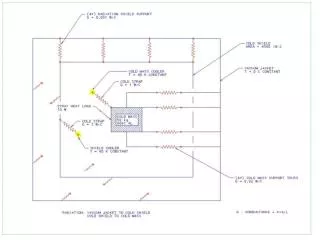
Steady state issues Systems: • Cooling channels must be close to plasma: (e < 10 mm) • Joining methods, erosion • Surveillance of large area with fast response (< 1 s), hot spots.. IR cameras • New requirements on diagnostics, fuelling and heating and CD systems (LHCD, ICRH, ECRH, NNBI) New physics: • Vloop ~ 0, no Ware pinch • Slow interplay between particle/energy transports and current profile • Irreversible bifurcations stable conditions require feedback Active new area of research • Presently: Tore Supra, TRIAM-1M, LHD, HT7… • New devices: W7X, KSTAR, EAST, SST1 and ITER (all superconducting) J. Jacquinot, 20th IAEA Fusion Energy Conference, Vilamoura, Portugal, 1/11/2004
Outboard movable bumper Vessel protection (148 panels) Bumpers (6 pairs) TPL TORE SUPRA 2004 • Toroidal Pumped Limiter; heat exhaust capability 15 MW (10 MWm-2) • Vessel protection against thermal radiation and plasma contact • 10 actively cooled neutralizers below the TPL; max. flux 15 MW/m2; • total pumping speed 20 m3/s • 30 Diagnostics (actively cooled also) J. Jacquinot, 20th IAEA Fusion Energy Conference, Vilamoura, Portugal, 1/11/2004
LH Power (MW) t =20s – 250 s Transformer flux (Wb) Hard-X 60-80 keV (a.u.) Te(0) = 4.8 keV q Line density (x1019m-2) Ti(0) =1.6 keV Neutron (x1010/s) Zeff ~2 Vloop = 0 for > 6 minutesinjected energy of 1.1 GJ (Van Houtte, poster EX/P4-14) Stable plasma until 258s then MHD activities switched on (no effect on global confinement) J. Jacquinot, 20th IAEA Fusion Energy Conference, Vilamoura, Portugal, 1/11/2004
Fast particle losses Radiation 23% Convection 71% Heat Exhaust ~ 50% on the TPL (7 m2) 25% on the first wall panels (75 m2 with the bumpers) 25% shared between the outboard limiter and antennas Beware of fast particles: ripple and later alphas! J. Jacquinot, 20th IAEA Fusion Energy Conference, Vilamoura, Portugal, 1/11/2004
Particle retention(Tsitrone, EX10-2) dNp/dt = Finj – Fpump –F in vessel Phase 1: Decreasing retention rate filling carbon porosities Phase 2: Constant retention rate : 2 1020D s-1 (= 50% of injected flux) co-deposition observed but not enough (deep penetration in carbon?) In vessel inventory : up to 8 1022 D for 6 mn (>> saturation of 15 m2 of carbon) Identical shot to shot behaviour. No saturation of in-vessel retention after 15 minutes of cumulated plasma time J. Jacquinot, 20th IAEA Fusion Energy Conference, Vilamoura, Portugal, 1/11/2004
0.6 Ip (MA) 0.4 Vloop (V) 0.2 2 <ne> (1019m-3) 1 <M> = 1.5 1020 atoms 0 V = ~ 0.5km/s 0.1 0.0 LH power (MW) 3 2 1 0 0 20 40 60 80 100 120 Time (s) Pellet injection during 2 minutesin presence of LH LH power notching allows penetration of 155 pellets Very stable speed of 0.5 km/s • Relevant for ITER: • Reliable screw extruder • Pneumatic acceleration does not require large pumping system (<15 mbar.l for 2mm pellets up to 800 m/s) J. Jacquinot, 20th IAEA Fusion Energy Conference, Vilamoura, Portugal, 1/11/2004
Te (keV) r/a =0.2 LH power (MW) Radial structure, low frequency (a few Hz) Slow temperature oscillations Poster EX/P6-16 Imbeaux et al. Non linear interplay between transport and current profile at the onset of the core ITB RT control of current profile required (for ex, ECCD) J. Jacquinot, 20th IAEA Fusion Energy Conference, Vilamoura, Portugal, 1/11/2004
PLH (MW) transformer flux (Wb) Line density (1019 m-2) ECCD phase Ip (MA) 0.5 MW of LH power replaced by 0.7 MW of EC power to drive80 kA Synergy when LH and EC waves absorbed at same location Evident synergy ECCD &LHCD at Vloop = 0 (Giruzzi et al EX/P4-22) Promissing for NTM control using ECCD in ITER J. Jacquinot, 20th IAEA Fusion Energy Conference, Vilamoura, Portugal, 1/11/2004
L-mode discharges Combined LHCD & ICRH • Achieving 10 MW / 10s pulses • Exhibit good L-mode, HL up to 1.7, when optimzing H minority concentration (nD/ne ~6%): • Spontaneous toroidal co-rotation • ITG & TEM stabilized by EB shear (r/a <0.6) (C. Fenzi-Bonizec et al, 31st EPS Conf) J. Jacquinot, 20th IAEA Fusion Energy Conference, Vilamoura, Portugal, 1/11/2004
LH Power (MW) Zeff Transformer flux (Wb) t= 20s – 350s LCFS Density peaking, n(0) / <n> ne (x1019m-3) VWare @ r/a = 0.2, 0.4, 0.6 Magnetic axis from reflectometry Peaked density profilein absence of Ware pinch Supression of Ware pinch over 6 minutes R Sabot et al EX/P6-25 No central source; Vneo ~10-3 m/s cannot explain peaked ne profile G.T. Hoang, Phys. Rev. Lett. 90 (2003) J. Jacquinot, 20th IAEA Fusion Energy Conference, Vilamoura, Portugal, 1/11/2004
r/a =0. 3 - 0.6 r/a =0. 3 - 0.6 q/q (m-1) • Te/ Te • (m-1) - n/n (m-1) - n/n (m-1) Circles: Te/Ti =1.3 Diamonds: Te/Ti =2.1 CT -0.2 Cq 0.8 CT -0.15 Cq 0.8 - Te/ Te (m-1) q/q (m-1) Turbulent pinch coefficients (G.T Hoang, EX8-2) n/n = - Cqq/q + CTTe/Te q/q term dominates,consistent with TEM driven transport simulations G.T. Hoang, Phys. Rev. Lett. 93 (2004) X. Garbet, Phys. Rev. Lett. 91 (2003) J. Jacquinot, 20th IAEA Fusion Energy Conference, Vilamoura, Portugal, 1/11/2004
qedge = 9 qedge = 14 BRW model Exp. BRW model Exp. With turbulent pinch Q ~13 Q ~10 assuming flat ne Extrapolation to ITER Tore Supra: n ~ 1/q0.5 As found by Boucher, Rebut, Watkins for JET TEMs expected in ITER as in Tore Supra (similar effective collisionality related to detrapping of electrons) Peaked ne Fusion Power increased to 530 MW instead of 400 MW with a flat ne profile(ref. scenario) J. Jacquinot, 20th IAEA Fusion Energy Conference, Vilamoura, Portugal, 1/11/2004
100 GJ TRIAM-1M 10 GJ 10000 100 MJ 1GJ Tore Supra CIMES Plasma duration (s) ITER 1000 1.07 GJ 6 min 18 100 LHD JET JT60 10 10 kW 100 kW 1MW 10 MW 100 MW Injected Power Progress in Long Pulse Operation J. Jacquinot, 20th IAEA Fusion Energy Conference, Vilamoura, Portugal, 1/11/2004
LHCD system 700kW, 1000s, 3.7GHz Klystrons 400kW, 600s, gyrotrons ICRH antenna with conjugate matching Passive Active Module (PAM) Tore Supra ongoing upgrades J. Jacquinot, 20th IAEA Fusion Energy Conference, Vilamoura, Portugal, 1/11/2004
Conclusions • Routine SS operation with superconducting coils, RF heating and thin walled PFC’s • Coping with detailed in-vessel power deposition is tough! • Slow non-linear oscillations/bifurcations • Unexplained long lasting in-vessel retention of D (low density regime) • Turbulent particle pinch documented A gift from mother nature to ITER ? • Exciting scientific developments in Cadarache in preparation of ITER J. Jacquinot, 20th IAEA Fusion Energy Conference, Vilamoura, Portugal, 1/11/2004
Movie J. Jacquinot, 20th IAEA Fusion Energy Conference, Vilamoura, Portugal, 1/11/2004
G.T. Hoang, EX8-2Turbulent Particle Transport in Tore Supra Fri. • E. Tsitrone, EX10-1Deuterium retention in Tore Supra long discharges Sat. • D. van Houtte, EX/P4-14Real Time Control of Fully Non-Inductive 6 minute, 1 Gigajoule Plasma Discharges in Tore Supra Thurs. • G. Giruzzi, EX/P4-22Synergy between EC and LH Current Drive on Tore SupraThurs. • F. Imbeaux, EX/P6-16Non-linear electron temperature oscillations on Tore Supra: experimental observations and modelling by the CRONOS codeFri. • R. Sabot EX/P6-25Measurements of density profiles and density fluctuations in Tore Supra with refclectometryFri. • T. LoarerEX/P5-22 Overview of gas balance in Plasma Fusion devices Fri. • G. Martin, EX/10-6RcDisruption&Mitigration in Tore SupraSat. • Ph. Ghendrih, TH 1-3Relaxation & Transport in Fusion Plasmas Thurs. • Y. Sarazin, TH/P6-7Interplay between density profile and zonal flows in drift kinetic simulations of slab ITG turbulent Fri. & Sat • Ph. Ghendrih, TH/1-3RaScaling Intermittent Cross-Field Particle Flux to ITER Thurs. • S. Benkadda, TH/1-3RbNonlinear Dynamics of Transport Barrier Relaxations in Fusion Plasmas Thurs. • M. Bécoulet, TH/1- 3Rc Non-linear Heat Transport Modelling with Edge Localized Modes and Plasma Edge Control in Tokamaks Thurs. • G. Falchetto, TH/1-3RdImpact of Zonal Flows on Turbulent Transport in Tokamaks Thurs. J. Jacquinot, 20th IAEA Fusion Energy Conference, Vilamoura, Portugal, 1/11/2004