Download
1 / 8
90 likes | 275 Views
Ion Cyclotron Wall Conditioning (ICWC) on Tore Supra. D. Douai, A.Lyssoivan 1 , T. Wauters, E. de la Cal 2 , G. Lombard, B. Pegourié, E. Tsitrone, S. Brémond, and Tore Supra Team. 1 Laboratory for Plasma Physics – ERM/KMS, Association EURATOM-BELGIAN STATE, 1000 Brussels (Belgium)

E N D
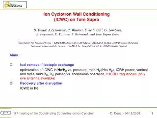
Ion Cyclotron Wall Conditioning (ICWC) on Tore Supra D. Douai, A.Lyssoivan1, T. Wauters, E. de la Cal2, G. Lombard, B. Pegourié, E. Tsitrone, S. Brémond, and Tore Supra Team 1Laboratory for Plasma Physics – ERM/KMS, Association EURATOM-BELGIAN STATE, 1000 Brussels (Belgium) 2Laboratorio Nacional de Fusión – CIEMAT, Av. Complutense 22, E- 28040 Madrid (Spain) Aims : • fuel removal / isotopic exchange optimization of ICWC in He/H2vs. pressure, ratio H2/(He+H2), ICRH power, vertical and radial field BR, BV, pulsed vs. continuous operation, 2 ICRH frequencies (only one antenna available) • Recovery after disruption ICWC in He
ICWC discharges in He and He/H2 • Gas breakdown obtained in He for pTore>2,5.10-2 Pa and PICRF <100kW • Stable Operation of Q2 antenna during 1 minute, despite a few problems of matching of Q2. • Above ~60 sec., loss of antenna matching loss of the ICWC discharge Determination of gas breakdown conditions (pTore, PICRF) He-30%H2, PICRF=40kW, pTore=4.10-2 Pa, 60 sec. long #43463 #43426
Phasing between antenna straps H2/(He+H2)=0.15, PICRF=60 kW • Coupling (h=PRF-pl /PRF-G) improved in monopole operation of ICRF antenna p-phasing h= 0.15 0-phasing h= 0.66 tbd= 33 ms tbd= 210 ms
Addition of Bv and Br rotating poloidal field • Application of sinusoidal Bv and Br, p/2 • Induced currents on non-selected poloidal field coils • Unperfected rotation of ICWC conditioning discharges #43532 #43532 #43532
Isotopic exchange and recovery nH/[nH+nD] in ohmic shots ohmic shot after 15+3’ ICWC after 15+3’ ICWC #43485 Reference ohmic shot before ICWC • high isotopic exchange after ~15 min. ICWC in He-H2 • Recovery to ohmic plasma after 3 min. He-ICWC discharge • Ohmic shot after He-H2-ICWC : no fuelling natural density from Nl=4,5 4.1018 m-2 radiative power fraction FPrad = 50%, as usual metallic impurities level as usual
Recovery after disruption disruptions Ohmic shots ICWC • 2 disruptions on outboard poloidal limiter (20 MA/sec. et 90 MA/sec.) • Pulsed ICWC discharge (2 sec. ON / 10 sec. OFF) in He • Each time, recovery after only 1 ICWC discharge in He (~10 pulses of 2 sec.) Disruption on outboard poloidal limiter at Ip=1,2 MA #43529 Non sustained breakdown
Low ohmic current pulsed discharges (“Taylor-like”) HD D2 Pure He-ICWC Recovery after disruption, comparison with other techniques • High HD (and D2,…) partial pressures measured in He-ICWC discharges • HD Desorption rate ~ 3.1018 s-1 Partial pressures (from mass spectrometer)
Conclusion • Stable operation of Q2 antenna at PICRF=60kW,during ~60 sec., loss of the ICWC discharge above 1 minute • Operation in 0-phasing improvement of antenna coupling • High isotopic exchange measured after He-H2-ICWC discharges • Recovery after disruption : actual score 2:0 for ICWC, to be continued… HD desorption rates ~ 3.1018 s-1 • Still many data need to be analyzed (Mass spectrometry, ICRF data, Interferometry, Reflectometry, Ha emission, Neutral Particle Analyzer…) • Possible improvements : • to improve Q2 matching (auto-tuning for PICRF<0,5MW) • to optimize the poloidal field configuration more interactions of ICWC discharges with different walls (toroidal and poloidal limiters,…) • to adapt some diagnostics (Langmuir probes, Retarding Field Analyzer) • ICWC discharges in D2