Download
1 / 41
410 likes | 565 Views
IFU Management Meeting. LAM – 15/10/04. Introduction (olf). Recall of the development History (Olf). Pour info – coût prototype: ~6 my : 360k€ Vacuum chambers; vibration tools: ??? ~150k€ hardware Test equipment: ~30k€ Travel: ? Total: ~600k€ (ESA funding : ~300k€).

E N D
IFU Management Meeting LAM – 15/10/04
Recall of the development History (Olf) • Pour info – coût prototype: • ~6 my : 360k€ • Vacuum chambers; vibration tools: ??? • ~150k€ hardware • Test equipment: ~30k€ • Travel: ? • Total: ~600k€ (ESA funding : ~300k€)
Lessons Learned from the prototype development • R&T development spirit of LAM Team where the contract was more fly hardware delivery type ( ESA did not refocus during the study) • Small experience in structural dynamic analysis • CNRS difficulties to manage industrial kind of contract • Laboratory has no autonomy • The prototype is finished and the core technology is validated
How to move for the NIRSPEC-IFU development • Needs of phase B/C/D industrial management type • Needs of high level reference support for dynamical analysis study • CNRS administration constraint not adapted for industrial sub-contract • Refocusing on our core activities
4 1 3 2 Slicer Principle How to rearrange 2D field to enter spectrograph slit: • Field divided by slicing mirrors in subfields telescope pupil on the pupil mirrors • Aligned pupil mirrors • Sub-field imaged along an entrance slit Courtesy: JR Allington Smith
Slicer unit optical design for the IFS Slit Mirrors Pupil mirrors Slicer mirror Entrance Pupil
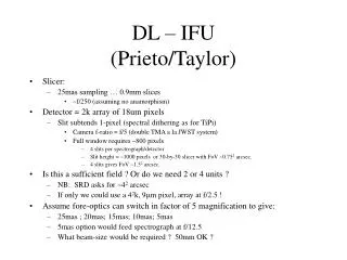
Slicer unit optical design for the IFS • Radius of curvature: ~ 150 mm • Tilt in Y: +/- 3.7° • Tilt in X: from 3.3 to 9° • Thickness: 900 µm • Width: 27 mm
Slicer unit optical design for the IFS: pupil mirror 300µm • Pupil mirror pitch: 2.754 mm • Pupil oversizing in spectrograph: <2 • Tilt Y: +/- 3.7° • Tilt X: 3.65° –> 6° • Curvature Radius: ~24.5mm
Slicer unit optical design for the IFS: slit mirror 500µm • Pitch: 2.754 mm • Curv. radius: 26.5 mm • Tilt Y: 0° • Tilt X: 6.5°
Pupil mirror array Dummy Stack Slit mirror array Active Stack Heel Stacksupport Thrust cylinders Substructure Steeringmirror Main structure Design Overview
Clamp Slicer Stack 2 Dummy slices 10 Active slices 18 dummy slices Clamps
Crosstalk +/-40µm relative for a specification of +/- 120µm
Slits separation Plots of the intensity profiles in the regions between the pseudo-slits. Lowest contour in the plots corresponds roughly to ~1% of the peak intensity (50 for a peak intensity of ~3000).
ESA ASTRIUM concern • ESA and Astrium presentation
Design & development approach • Phase B: • Design • Analysis (optical performance, stray light analysis, structural static and dynamic, thermal) • Test Plan preparation • Technological development: • 30+3 optical bonding release (for statistical approach) • 30+3 Hydroxil bonding release • 40 slices stack with optical bonding (vibration, thermal, shock) • 40 slices stack with Hydroxil bonding (“”) • Opto-mechanical mount for pupil lines (thermal, vibration, shock) • Opto-mechanical mount for flat folding mirror (thermal, vibration, shock)
Design & development approach • Phase C/D: • STM: for dynamical model calibration, opto-mechanical demonstrator verification, and delivery at Astrium • EQM: end to end optically functional for 9 channels, structural fully representative, interface representative; qualification in vibration, optical performance at operating temperature, thermal cycling, and shock • FM: Environmental tests at acceptance level, acceptance optical test at operation temperature, characterization at operating temperature
Technology development plan • 33 samples of pupil mirrors optical bonded: • 33 acceptance tests • 33 cryo cycling (22°K) • 30 tests up to release at atmosphere pressure • 3 tests up to release in vacuum • 33 samples of pupil mirrors hydroxil bonded: • 33 acceptance tests • 33 cryo cycling (22°K) • 30 tests up to release at atmosphere pressure • 3 tests up to release in vacuum
Technology development plan • 40 slices stack optical bonded: • 15 thermal cycling (survival - IFU-284) • Vibration qualification tests (survival - specification?) • Shock tests (survival - specifications?) • 40 slices stack hydroxil bonded: • 15 thermal cycling (survival - IFU-284) • Vibration qualification tests (survival - specification?) • Shock tests (survival - specifications?)
Technology development plan • Opto mechanical mount of pupil mirror lines on INVAR: • Representative zerodur support (similar mass than support plus pupil mirror) • Opto-mechanical mount (representative) • Vibration test (survival - specifications?) • Thermal cycling (survival - IFU-284) • Shock test (survival - specifications?) • Opto mechanical mount of folding mirror: • Representative element • Opto-mechanical mount (representative) • Vibration test (survival - specifications?) • Thermal cycling (survival - IFU-284) • Shock test (survival - specifications?)
Product Breakdown / procurement approach • Image slicer: • Slicer unit + pupil line + slit line • No opto-mechanical mount • Test structure for acceptance @RT • Folding mirror: • Mirror plus opto-mechanical mount • Test acceptance @RT and @OP • Toroidal mirrors: • Two mirrors together • Optomechanical mount • Test structure for acceptance @RT • Structure: • STM: refurbishing after tests • EQM + FM + Spare: to the same company
Verification approach • Sub system acceptance: • Slicer, mirror lines: vibration (level?) + thermal cycling • Folding mirror + mount: vibration (level?) + thermal cycling + flatness @OP • Toroidal mirrors: optical performances mounted together @RT • Slicer + pupil +slit: optical performance together @RT
Verification approach • EQM:
Verification approach • FM:
Planning • KO: Nov 30th • PDR: Sept 05 • … a remplir avec le SOW que j’ai pas… michel?