Download
1 / 23
230 likes | 443 Views
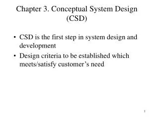
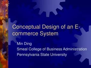
Conceptual System Design Step 2 - Functional Analysis. INCOSE Sec. 4.3 DSMC Chapter 5. Why Modeling?. We build models of complex systems because we cannot comprehend any such system in its entirety. As the complexity of systems increase, so does the importance of good modeling techniques.

E N D
Conceptual System Design Step 2 - FunctionalAnalysis INCOSE Sec. 4.3 DSMC Chapter 5 Eng 202 Concept - 1
Why Modeling? • We build models of complex systems because we cannot comprehend any such system in its entirety. • As the complexity of systems increase, so does the importance of good modeling techniques. • A modeling language must include: • Model elements: fundamental modeling concepts and semantics • Notation:visual rendering of model elements • Guidelines: idioms of usage within the trade • There are many additional factors of a project’s success, but having a rigorous modeling language is one essential factor. Eng 202 Concept - 2
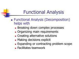
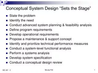
Functional Analysis • Defines what the system will do, not how it will do it • Supports mission and operations -concept analysis in defining: • Functional requirements (behavior) • Sequences • Interfaces • Grouping of functions • Perform a single task • Separable testable • Single entry and exit point • Simplify interfaces • Top-down decomposition • Each function is decomposed into subfunctions • Process iterated until system has been decomposed into basic subfunctions Eng 202 Concept - 3
Methodologies for Functional Analysis • Useful for both hardware and software systems • A complete system analysis generally requires some combination of these techniques • Models can be developed to represent system at many different levels depending • on purpose • Automated SE tools support modeling and simulation • - Executable models Eng 202 Concept - 4
What Representations to Use? • Multiple representations* are normally required to produce the information needed by the customers and developers • Common representations include • Behavior: What the system does • Physical: What the system is • Data or logical: Relationships among data • And many more • Each representation generally contains complementary information • No single view of requirements provides a complete understanding of them • “A Picture Is Worth 1024 Words” • Software Requirements, Karl E. Wiegers * Representation = model = view = description Eng 202 Concept - 5
Some Basic Principles • Every complex system is best approached through a small set of nearly independent views of a model. • No single view is sufficient. • Abstraction: the focus on relevant details while ignoring others, is a key to learning and communicating. • Every model may be expressed at different levels of fidelity. • The best models are connected to reality. • The choice of what model one creates has a profound influence upon how a problem is attacked and how a solution is shaped Eng 202 Concept - 6
CPU1 SW 1 CPU N SW N CPU1 CPU N The Need For a Common HW-SW SE • From a HW perspective, SW appears to be encapsulated in HW • From a SW perspective, especially distributed systems it looks the reverse • Either perspective is inadequate • Hardware world view of the system • Software world view of the system Eng 202 Concept - 7
Functional Flow Block Diagram (FFBD) The FFBD is structured to ensure that: • All life cycle functions are covered • Detailed step-by-step operational and support sequences for the system are defined • Proper sequencing of activities are established • Rules for common understanding • Multiple levels • Lower levels are expansions of top level • Numbering • Top level functions: 1.0. 2.0. 3.0,... • Name of function inside box Eng 202 Concept - 8
2nd level 3.1 Sense problems 3.2.1 3rd level 3.1.1 Dial 911 Sense intruders 1.2.2 3.1.2 & Alert neighbors & Sense water 1.2.3 3.1.3 Alert intruder Sense fires Alert residents FFBD - Home Protection System(Partial) Top-level 1.0 2.0 3.0 4.0 Install Turn on Protect home Checkout 3.2 Trigger alarms 3.0 3.2 3.1 Eng 202 Concept - 9
N2 Charts • Functions are on the diagonal • Outputs are on the horizontal • Inputs are on the vertical • The remaining squares represent the interface inputs and outputs • Where a blank exist there is no interface between the respective system functions Eng 202 Concept - 10
Example - Home Protection System Partial N2 Chart Eng 202 Concept - 11
Controls Inputs - transformed or consumed to produce outputs Ÿ Controls - specify conditions to produce correct Ÿ output Inputs Outputs Outputs - data or objects produced Ÿ Process Mechanisms - means that support execution Ÿ A0 Mechanisms Integrated Definition For Function Modeling (IDEF0) • Context Diagram – Top-level box represents boundaries of the system – Decomposed into decomposition diagrams • Decomposition Diagrams – IDEF0 diagrams which reveal more details Eng 202 Concept - 12
IDEF0 Model - Home Security SystemContext Diagram Eng 202 Concept - 13
IDEF0 Model - Home Security SystemDecomposition Diagrams Eng 202 Concept - 14
Finite-State Machines • Real-time systems and process ontrol applications can exist in one of a limited number of states at a given time • Finite-state machines • Two types of systems • Combinatorial: depends only on present inputs • Sequential: depends on the starting state and the history of the inputs • Every system can be described as a collection of state machines • Turing, 1936 • Difficult to ensure correct finite-state machine using natural language • All permitted state changes • No prohibited state changes • State -Transition Diagrams • Describe external behavior of system in response to stimuli Eng 202 Concept - 15
State-Transition Modeling • State • Abstraction of the attribute values and links held by an object. Specified between events. • Event • Something that happens at a point in time • Scenario • Sequence of events that occur during one particular execution of a system • State diagram • Relates events and states • Condition • Boolean function of object value • Initial State: Normal Event: Furnace catches fire Condition: If the temperature rises faster than 1 0C/second for 10 seconds Next state: Then we have a “fire condition”. Dial 911, sound alarm,... Eng 202 Concept - 16
Old State New State (old state, stimulus) (new state, response) State Matrix • Lists valid combination of attributes for every state Stimulus|response Eng 202 Concept - 17
State-Transition DiagramFire Protection System Monitor Eng 202 Concept - 18
Object Modeling Technique (OMT) • One of several Object Oriented Analysis (OOA) methods • Rumbaugh et al, 1991 • Represents and deals with 3 dimensions • Static structure in terms of states • Dynamic behavior in terms of sequence of events, states • Fuunctionality in terms of operations/transformation that occur Eng 202 Concept - 19
Object Model For Fire Protection Eng 202 Concept - 20
Event Traces • Time-dependent behavior of system • Logical ordering of events in a scenario • Event trace for fire scenario Eng 202 Concept - 21
Unified Modeling Language (UML) • UML is a visual modeling language for • specifying • documenting • constructing • visualizing • UML is object-oriented, component-based • UML is well suited for software-intensive systems • Tools available • Rose by Rational Co. • De-facto standard, multi-company standard Eng 202 Concept - 22
Unified Modeling Language (UML) In terms of the views of a model, the UML defines the following graphical diagrams: · use case diagram · class diagram · behavior diagrams · state diagram · activity diagram · sequence diagram · collaboration diagram · implementation diagrams · component diagram · deployment diagram These diagrams provide multiple perspectives of the system under analysis or development. The underlying model integrates these perspectives so that a self-consistent system can be analyzed and built. Eng 202 Concept - 23