Download
1 / 10
100 likes | 417 Views
Conceptual Design of CFETR Magnets System. Tokamak Machine Design Team. 2012.5.27 Hefei. Overview of Magnets System for CFETR. ITER. CFETR. CS Coil. TF Coil. PF Coil. The magnet system of CFETR consists of TF, CS and PF coils. The ITER magnet design is a good reference for CFETR.

E N D
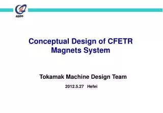
Conceptual Design of CFETR Magnets System Tokamak Machine Design Team 2012.5.27 Hefei
Overview of Magnets System for CFETR ITER CFETR CS Coil TF Coil PF Coil The magnet system of CFETR consists of TF, CS and PF coils. The ITER magnet design is a good reference for CFETR - 2 -
Magnetic field analysis for TF coil B for TF coils B for plasma central Contour distribution for B Maximum magnetic field for TF 10.6T magnetic field in plasma central 4.5T. - 3 -
TF coils for CFETR Parameters of TF coils coil inner & outer cross-section TF Conductor: Nb3Sn , 57 kA - 4 -
Calculation for Volt seconds of PF and CS coils Volt seconds is about 100Vs. The stray magnetic field not beyond 15GS at the plasma region PF and CS coils location and current Distribution for magnetic flux The maximum total magnetic field: 6.5T on PF2U. The maximum total magnetic field: 10.25T on the CS coils. Contour for the magnetic flux density - 5 -
PF1U/PF2U PF3U CS3U CS2U PF4U CS1U VACUUM VESSEL CS1L PF4L CS2L CS3L PF3L PF1L/PF2L Plasma equilibrium calculation and magnetic analysis for PF and CS coils Current of PF coils for equilibrium (MAT) Maximum total magnetic field: 6.4T for PF1/2U Maximum total magnetic field: 9.4T for CS - 6 -
Preliminary consideration for CS coils • 6 module consisting of Octa & dual-pancakes • 374 turns each module • Conductor design is similar as ITER: ~ 45 kA multi-stage Nb3Sn cable with central cooling channel, circular in square conduit CS Conductor Cross section of one CS module - 7 -
Preliminary consideration for PF coils • 400 turns in PF1U/PF2U/PF1L/PF/2L coil • 196 turns in PF3U/ PF3L coil • 154 turns in PF4U/ PF4L coil • Conductor: 40-50 kA NbTi multi-stage cable with central cooling channel. Cross section PF4U/PF4L Coil PF3U/ PF4U PF3L/PF4L Conductor PF1U/PF2U PF1L/PF2L Cross section of Conductor Cross section PF3U/PF3L Coil PF1U/PF2U PF1L/PF2L Coil - 8 -
STR feeder CC Feeder PF Feeder CS Feeder TF Feeder Magnets Feeder & Cryogenic system • Feeder design is similar with ITER • HTS-CLs will be adopted for Feeders • the total LHe value in cooling loops of magnet system around ~80 (m3) • Estimated heat load of magnet system is ~20kW @ 4.5 K • The Cryogenic system consist of Cryoplant & Cryodistribution system. The capacity of LHe Plan will be fixed late Layout of ITER magnets feeders - 9 -
Thanks for your attention! - 10 -