Download
1 / 18
180 likes | 430 Views
Radiation Hardness Assurance. Stewart Harris. Outline. Radiation Hardness Assurance Plan Summary of Radiation Effects on CCDs Mitigation Efforts CCD Radiation Testing Test Plan Results of Test Conclusions. Radiation Hardness Assurance.

E N D
Radiation Hardness Assurance Stewart Harris
Outline • Radiation Hardness Assurance Plan • Summary of Radiation Effects on CCDs • Mitigation Efforts • CCD Radiation Testing • Test Plan • Results of Test • Conclusions NCKU UCB Tohoku CCD Radiation S. Harris
Radiation Hardness Assurance • Radiation tolerance for all electronics is established by: • History of use at SSL • Manufacturer data on design and QC • SSL testing • Total ionizing dose requirement: • 20 krad NCKU UCB Tohoku CCD Radiation S. Harris
FPGA Actel RH1280-CQ172B A/D Converter SEI 9240LPRP DSP Temic TSC21020F SRAM Honeywell HX6228TBRC EEPROM SEi 28C010TRPFB-15 PROM Raytheon R29793SM/883 Microprocessor Intersil HS1-80C85RH-Q DC-DC Converter Modular Devices 2680R-S12F Op Amps Intersil HS7B-1135RH-Q Analog Devices AD648TQ/883B Multiplexer / Switches Intersil HS1-508BRH Siliconix DG613AK/883 RS-422 Driver/Receiver Intersil HS9-26CT31RH-Q Intersil HS9-26CT32RH-Q Logic National Semi. ‘AC/883 Family Critical EE Parts Selection Partial List NCKU UCB Tohoku CCD Radiation S. Harris
CCD Specifications • CCD • Type: 1024 x 1024, frame transfer • Manufacturer: Dalsa, IA-D4 • Antiblooming: Vertical anti-blooming (VAB) • Primary mode: 512 x 128 (binned 2x2 and masked) • Pixel size (unbinned): 12 µm x 12 µm • Pixel size (binned): 24 µm x 24 µm • # of Outputs: 2 • Pixel readout rate: 8 MHz • Radiation tolerance Unknown NCKU UCB Tohoku CCD Radiation S. Harris
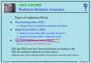
Radiation Effects on CCDs • Two classes of radiation damage • Bulk Damage: Displacement of Si atoms within lattice • Caused by energetic particles • Effects: • Creates charge traps in bulk Si • Loss of charge transfer efficiency (CTE) • An increase in bulk dark current and in its non-uniformity • Temporal fluctuation dark current generation (Random Telegraph Signal) • Ionization Damage: Charge buildup in SiO2 layer • Caused by all ionizing radiation • Effects: • An increase in surface dark current • Flat band voltage shifts NCKU UCB Tohoku CCD Radiation S. Harris
Design Mitigation Steps • Shielding (as much as possible) • Best approach to minimize all effects • Appropriate Design Margins • Can minimize effects associated with voltage shifts • Can minimize effects of dark current increase • Also can employ dither clocking during long exposures • Cooling of CCD • Reduces dark current • Can reduce effect of charge traps • Radiation Testing to verify Effects on Dalsa CCD NCKU UCB Tohoku CCD Radiation S. Harris
CCD Radiation Test • Test items • Dalsa IA-D4 CCDs, S/N 200550 & 70070 • Test configuration • CCD's mounted on vector board within aluminum chassis, biased at 22V (powered by three 9 V batteries) • Radiation source: LBL 88” Cyclotron, Cave 3b • Test Plan • Establish baseline CCD performance in test bed camera • Expose CCDs to 55MeV protons, fluence 1x10⁸ p+/cm2 • Measure CCD change in imaging performance • Expose CCDs to 55MeV protons, fluence 1x10⁹ p+/cm2 • Measure CCD change in imaging performance NCKU UCB Tohoku CCD Radiation S. Harris
Radiation Test Set Up CCD Test Fixture Test Fixture mounted on beam line7 Aug 2000 NCKU UCB Tohoku CCD Radiation S. Harris
Summary of Test Results • After Exposure to 1x10⁹protons/cm2 fluence: • Dark signal increased by factor of ~10 • As measured at room temperature • Dark signal non-uniformity increased by factor of ~5 • Full well capacity decreased by factor of ~2 • likely due to bias shifts • Resolution decreased slightly • perhaps due to CTE degradation NCKU UCB Tohoku CCD Radiation S. Harris
Changes in Dark Signal - 1 Pre-Radiation Post-Radiation1x109 p+/cm2 NCKU UCB Tohoku CCD Radiation S. Harris
Changes in Dark Signal - 2 NCKU UCB Tohoku CCD Radiation S. Harris
Dark Signal Extrapolation Acceptable Level NCKU UCB Tohoku CCD Radiation S. Harris
Change in Full Well Capacity 100ke- 50ke- Before Radiation After Radiation NCKU UCB Tohoku CCD Radiation S. Harris
Resolution Test - 1 • Resolution Chart • measure CTF • both binned and not binned • Spatial Frequencies • max 42 lp/mm NCKU UCB Tohoku CCD Radiation S. Harris
Resolution Test - 2 NCKU UCB Tohoku CCD Radiation S. Harris
Data - Resolution Test - 3 Image segments - Unbinned Before Radiation After Radiation NCKU UCB Tohoku CCD Radiation S. Harris
Conclusions for Use of Dalsa CCD Preliminary • For the radiation environment tested: • While dark signal grows dramatically, the planned level of CCD cooling should be sufficient to counteract this problem • Loss of full well capacity is mitigated by operating in binned mode, which is principal mode of operation • CTE degradation doesn’t appear to be a major problem • Dalsa CCD appears to satisfy the requirements of this radiation environment NCKU UCB Tohoku CCD Radiation S. Harris