Download
1 / 77
791 likes | 1.1k Views
Learn about specifications, protective devices, and maintenance practices for distribution transformers to prevent failures. Understand the working principle, efficiency, cooling types, and parallel operations. Discover the parts, routine tests, and maintenance procedures essential for transformer longevity.

E N D
Welcome to the Presentation onSpecificationsProtective devices and Maintenance Operation & Maintenance of Distribution Transformers, Prevention of Failures & Repairs (C&D employees) (DIST TFS)
WHAT IS A TRANSFORMER? • Transformer is a static device which transforms A.C. Electrical power from one voltage to another voltage keeping the frequency same by electromagnetic induction.
Power Transformers • Transformers Capacity In A System: Generally 6 to 8 times the installed capacity • Working Principle: Static piece of apparatus used for transferring power from one circuit to another without change in frequency. It can raise or lower the voltage with a corresponding decrease or increase in current.
Ideal Transformer : No Losses • EMF equation of a Transformer : E1=4.44fN1øm E2=4.44fN2øm where N1=No. of turns in Primary N2=No. of turns in Secondary øm= Maximum flux in the core in Webers
Voltage Transformation ratio (k) : E2/E1 = N2/N1 = k • Step up Transformer : k>1 • Step down Transformer : k<1 • Regulation : %Regulation = ((E2-V2) / E2) * 100 where, E2 = Secondary Terminal Voltage at no load V2 = Secondary Terminal Voltage at load
Losses in Transformers : • No load losses = Hysteresis loss + Eddy current loss • How can we minimize these losses ? • By using steel of high silicon content with thin laminations . • The input power of a transformer, when on no load measures the core loss. • Load Losses : I2R losses + Stray losses(losses occurring in the mechanical structure and winding conductor due to the stray fluxes). These are measured by short circuit test.
Efficiency: % efficiency = ((output)/ input) * 100 • Condition of maximum efficiency : Iron loss = copper loss. • Transformers are among the most efficient machines. • In lower capacity ranges: Around 95% efficiency • In higher capacity ranges : 99% is achievable. • Auto Transformer : Has a single continuous winding which is used for the input and output voltages. Used where transformation ratio differs a little from unity.
Components of Transformer • Windings • Core • Bushings • Conservator • Breather • Buchholz Relay • OLTC • Oil level Indicator • Thermometers • Various protective devices
Bushings Two types: • Porcelain : Upto 36 kv • Condenser
Various Types of Cooling in Transformers • Various Types of Cooling in Transformers: • ONAN : OIL NATURAL AIR NATURAL • ONAF : OIL NATURAL AIR FORCE • OFAF : OIL FORCE AIR FORCE • OFWF : OIL FORCED WATER FORCED • Type of cooling vs Rating : • OFAF :100% • ONAF :60% • ONAN :40%
Parallel Operations of Transformers • Satisfactory performance requires that they have : • The same voltage ratio. • The same per unit(or percentage) Impedance. • The same polarity. • The same phase sequence and zero relative phase displacement.
(3) and (4) are absolutely essential. (1) Must be satisfied to a closer degree. (2) The more near , better will be the load division. • Tap Changers : Two types: • Off-Load Tap Changer. • On-Load Tap Changer.
DISTRIBUTION TRANSFORMER • TRANSFORMER WHICH IS USED FOR THE PURPOSE OF DISTRIBUTION OF POWER. • 11KV/433V is the standard voltage rating. • STANDARD KVA ratings are 25,63,100,160,200,250,315,400,500,630,750,1000, 1250,1500,2000,2500 KVA. • IS-2026 is the INDIAN NATIONAL STANDARD.
MAIN FEATURES • Outdoor,oil cooled, 3 phase,50hz • Primary is delta connected and secondary is star connected. • Naturally cooled (ONAN type). • Amongst all the types of transformers this is the most required and most used type.
PARTS OF TRANSFORMER • MAIN TANK • RADIATORS • CONSERVATOR • EXPLOSION VENT • LIFTING LUGS • AIR RELEASE PLUG • OIL LEVEL INDICATOR • TAP CHANGER • WHEELS • HV/LV BUSHINGS • FILTER VALVES • OIL FILLING PLUG • DRAIN PLUG • CABLE BOX
ROUTINE TESTS • Oil BDV TEST. • Oil breakdown voltage is checked as per IS-335. • 100 mm L X 70 mm B X 80 mm Ht. glass pot. • 500ml Oil sample. • Spherical electrodes with gap of 2.5 mm • Recommended value : 60KV • Equipment used : OIL BDV TEST SET.
MAINTENANCE OF TRANSFORMER • Transformer is the heart of any power system. Hence preventive maintenance is always cost effective and time saving. Any failure to the transformer can extremely affect the whole functioning of the organization.
MAINTENANCE PROCEDURE • OIL : • Oil level checking. Leakages to be attended. • Oil BDV & acidity checking at regular intervals. If acidity is between 0.5 to 1mg KOH, oil should be kept under observation. • BDV, Color and smell of oil are indicative.
MAINTENANCE PROCEDURE • Sludge, dust, dirt ,moisture can be removed by filtration. • Oil when topped up shall be of the same make. Otherwise it may lead to sludge formation and acidic contents. • Insulation resistance of the transformer should be checked once in 6 months. • Megger values along with oil values indicate the condition of transformer.
MAINTENANCE • BUSHINGS: • Bushings should be cleaned and inspected for any cracks. • Dust & dirt deposition, salt or chemical deposition, cement or acid fumes depositions should be carefully noted and rectified.
MAINTENANCE • Periodic checking of any loose connections of the terminations of HV & LV side. • Breather examination. Dehydration of Silica gel if necessary. • Explosion vent diaphragm examination. • Conservator to be cleaned from inside after every three years. • Cleanliness in the transformer yards with all nests, shrubs removed.
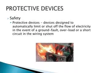
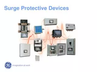
PROTECTION OF TRANSFORMERS • HT fuse & D.O. fuse. • LT circuit breaker. • HORN GAPS & Lightning Arrestor. • Breather.
FAILURES & CAUSES • Insufficient Oil level. • Seepage of water in oil. • Prolonged Over loading. • Single Phase loading. • Unbalanced loading. • Faulty Termination (Improper sized lugs etc) • Power Theft. • Prolonged Short Circuit. • Lack of installation checks.
FAILURES & CAUSES • Faulty design • Poor Workmanship • Improper formation of core. • Improper core bolt insulation. • Burr to the lamination blades • Improper brazing of joints. • Burr /sharp edges to the winding conductor. • Incomplete drying. • Bad insulation covering. • Insufficient cooling ducts in the winding.
FAILURES & CAUSES • Bad Quality of raw material. • Transit damaged transformers. • After failure, transformer is removed and replaced with new/repaired one without removing the cause of failure which results in immediate or short time failure.
Specifications for Distribution Transformers up to 100 KVA • The distribution transformers shall comply with the latest versions of Indian Standard Specifications IS 1180(part1) and IS 2026 • The Standard Ratings shall be 16, 25, 63 and 100 KVA • No load voltage ratios shall be as follows: • (a) 11000/433-250 volts for 16, 25, 63 and 100 KVA • (b) 10450/433-250 for 100 KVA only, whenever specified • No taps are to be provided in these transformers
Winding Connections and Vectors • The primary winding shall be connected in delta and the secondary winding in star ( Vector symbols Dy 11), so as to produce a positive displacement of 30 deg from the primary to the secondary vector of the same phase. The neutral of the secondary winding shall be brought to a separate insulated terminal. • The following standars fittings shall be provided • (a) Two earthing terminals • (b) Oil level gauge indicating three positions of oil, marked as follows: • Minimum( -5 deg C) • 30 deg C • Maximum (98 deg c) • (c) Lifting lugs
The distribution transformer forms a link between the consumers and primary distribution • Dielectricstrength of transformer oilshallbechecked once in a year • Acidity of transformer oilshallbechecked once in a year • Oillevelshallbechecked once in a month • Over loadingshouldbeavoided by checking Tong Tester Readings.
Distribution Transformers (DTRs) • Most rugged of all electrical equipment • All parts are tightly clamped • No rotating or moving parts inside • Shall be least prone to failure • In a number of Indian Power Utilities, the rate of failure is high (20 to 30% annually)
Equipment Life Cycle • Specification – Design – Manufacture – Transport – Erect – Commission – Operate – Protect – Maintain
MAINTENANCE TECHNIQUES • The maintenance techniques to be adopted should meet the following criteria: • Field staff should be able to carry out such tests and interpret the test results • Testing procedure to be evolved after detailed discussions with the supplier of the equipment and testing equipment • Written procedure to be made available to the operating staff
Maintenance of Equipment should Include • Diagnostics • Overhauls • Painting • Mechanical Aspects • Use of correct lubricants as specified by the manu- facturer • Availability of adequate spare parts
Responsibilities for Maintenance of Distribution Transformers
Responsibilities for Maintenance of Distribution Transformers
Responsibilities for Maintenance of Distribution Transformers
Responsibilities for Maintenance of Distribution Transformers