Chapter 7: Entity-Relationship Model
Chapter 7: Entity-Relationship Model. Overview of the Design Process. Creating a database application Design of the database schema Design of the programs that access and update the data Design of a security scheme to control access to data
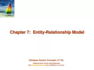

Chapter 7: Entity-Relationship Model
E N D
Presentation Transcript
Overview of the Design Process • Creating a database application • Design of the database schema • Design of the programs that access and update the data • Design of a security scheme to control access to data • Two major pitfalls to avoid in designing a database schema • Redundancy • repeating information data inconsistency • Incompleteness • difficult or impossible to model certain aspects of the enterprise
Main Phases of Database Design • Requirements collection and analysis • Understanding the needs of users and enterprises • Conceptual design • Choosing an abstract model like E-R Model • Conceptual schema: descriptions of the data requirements, entities, relationships, and constraints • Logical design • Converting the abstract model to implementation model • E-R model to relational model • Physical design • Specifying physical features of the database • File organization, index structures (Ch. 10 & 11)
E-R Model • Proposed by P. Chen in 1976 • Simple and powerful tool for the database design • Many database design tools draw on concepts from the E-R model • A database can be modeled as: • a collection of entities • relationships among entities
Entity Sets • Entity – an object that exists and is distinguishable from other objects • Example: specific person, company, event, plant • Entity set – a set of entities of the same type that share the same properties • Example: set of all persons, companies, trees, holidays • Attribute –descriptive properties possessed by all members of an entity set • Example: people have names and addresses
Entity Sets – instructor and student instructor_ID instructor_name student-ID student_name
Relationship Sets • Relationship – an association among several entities Example: 44553 (Peltier)advisor 22222 (Einstein)student entity relationship set instructor entity • Relationship set – a mathematical relation among n 2 entities, each taken from entity sets {(e1, e2, … en) | e1 E1, e2 E2, …, en En}where (e1, e2, …, en) is a relationship • Example: (44553,22222) advisor
Relationship Set – advisor advisor
Attribute of Relationship Set • An attribute can also be property of a relationship set
Natural Language Sentences to E-R Model • Rules of thumb for mapping natural language descriptions into E-R model: • Noun • Common noun entity set • Proper noun entity • Verb • Transitive verb relationship set • Intransitive verb attribute for entity • Adjective attribute for entity • Adverb attribute for relationship
E-R Diagrams • Rectangles represent entity sets • Diamonds represent relationship sets • Lines link entity sets to relationship sets • Attributes are listed inside entity rectangles • Underline indicates primary key attributes
Relationship Sets with Attributes • Dashed lines link attributes to the relationship sets
Roles • Entity sets of a relationship need not be distinct • Each occurrence of an entity set plays a “role” in the relationship • The labels “course_id” and “prereq_id” are called roles.
Degree of a Relationship Set • Degree of a relationship set • The number of entity sets that participate in the relationship • Most relationship sets in a database system are binary • You can define non-binary relationships
Attribute Types • Simple and composite attributes • Simple attribute: can not be divided into subparts • Composite attribute: composed of multiple subparts • Example: name = (first_name, middle_initial, last_name) address = (street, city, state, zip_code) • Domain – the set of permitted values for each attribute • Null value: a special value meaning “missing” or “unknown” • Some attributes are not allowed to have null values
Attribute Types • Single-valued and multivalued attributes • Single-valued attribute • Each attribute has a single value for an entity • Example: ID, name, address • Multivalued attribute • An attribute may have more than one value for an instance • Example: phone_number = {7287, 7288} • Derived attributes • Can be computed from other attributes • Example: age, given date_of_birth
Mapping Cardinality Constraints • Express the number of entities to which another entity can be associated via a relationship set • For a binary relationship set, the mapping cardinality must be one of the following types: • One-to-one • One-to-many • Many-to-one • Many-to-many
Mapping Cardinalities One-to-many One-to-one Note: Some elements in A and B may not be mapped to any elements in the other set
Mapping Cardinalities Many-to-many Many-to-one Note: Some elements in A and B may not be mapped to any elements in the other set
Mapping Cardinality Constraints in E-R diagram • Line types between the relationship set and the entity set • Directed line (): at most “one” (including 0) • Undirected line (—): “many” (including 0) One-to-one One-to-many Many-to-one Many-to-many
Participation Constraints • Total participation (indicated by double line): every entity in the entity set participates in at least one relationship in the relationship set • Example: participation of section in sec_course is total • every section must have an associated course • Partial participation: some entities may not participate in any relationship in the relationship set • Example: participation of instructor in advisor is partial
Cardinality Limits on Relationship Sets • Cardinality limits can indicate more complex participation constraints
Cardinality Constraints on n-aryRelationship • We allow at most one arrow out of a ternary (or greater degree) relationship • E.g., an arrow from proj_guide to instructor indicates each student has at most one guide for a project • If there is more than one arrow, there are two ways of defining the meaning. • E.g., a ternary relationship R between A, B and C with arrows to B and C could mean 1. each A entity is associated with a unique entity from B and C or 2. each pair of entities from (A, B) is associated with a unique C entity, and each pair (A, C) is associated with a unique B • To avoid confusion we outlaw more than one arrow
Keys • Keys for entity sets • A super key of an entity set is a set of one or more attributes whose values uniquely determine each entity. • A candidate key of an entity set is a minimal super key • ID is candidate key of instructor • Although several candidate keys may exist, one of the candidate keys is selected to be the primary key. • Keys for relationship sets • The combination of primary keys of the participating entity sets forms a super key of a relationship set. • (s_id, i_id) is the super key of advisor
Keys for Relationship Sets • Must consider the mapping cardinality of the relationship set when deciding what are the candidate keys (primary keys) Let R be a relationship set involving entity sets E1, E2, …, En. • Primary keys for binary relationship set (n = 2) • Many-to-many: PK(R) = PK(E1) U PK(E2) • Many-to-one/one-to-many: PK(R) = PK(“many”-side entity) • One-to-one: PK(R) = PK(E1) or PK(E2) • Primary keys for n-ary relationship set • No arrow edges: PK(R) = PK(E1) U PK(E2) U … U PK(En) • With an arrow edge: PK(R) = PKs of the entity sets not on the “arrow”-side • If the relationship set R’ is the relationship R with attributes {a1, …, am} • PK(R’) = PK(R) U {a1, …, am}
Removing Redundant Attributes • Suppose we have entity sets • Attribute dept_name in entity instructor is redundant • The attribute replicates information present in the relationship inst_dept, and should be removed from instructor • BUT: when converting back to tables, in some cases the attribute gets reintroduced, as we will see.
Weak Entity Sets • Weak entity set: an entity set that does not have a primary key • The existence of a weak entity set depends on the existence of an identifying entity set • It must relate to the identifying entity set via a total, one-to-many relationship set from the identifying to the weak entity set • Identifying relationship depicted using a double diamond • The discriminator(or partial key) of a weak entity set is the set of attributes that distinguishes among all the entities of a weak entity set. • We underline the discriminator of a weak entity set with a dashed line. • The primary key of a weak entity set = (the primary key of identifying strong entity set)+ (the weak entity set’s discriminator)
Exercise • Construct an E-R diagram for the following company enterprise. • A company has many employees. We store each employee’s name, SSN, address, salary, gender, and birth date. • The company is organized into departments. Each department has a unique name, a unique number, and a particular employee who manages the department. The department may have several locations. • An employee works for one department, and we keep track of the employee assignments. We also keep track of the direct supervisor of each employee. • Also, we want to keep track of the dependents of each employee for insurance purposes. We keep each dependent’s name, gender, birth date, and relationship to the employee.
Reduction to Relation Schemas • Entity sets and relationship sets can be expressed uniformly as relation schemasthat represent the contents of the database. • A database which conforms to an E-R diagram can be represented by a collection of schemas. • For each entity set and relationship set there is a unique schema that is assigned the name of the corresponding entity set or relationship set. • Each schema has a number of columns (generally corresponding to attributes), which have unique names.
Representing Entity Sets With Simple Attributes • A strong entity set reduces to a schema with the same attributesstudent(ID, name, tot_cred) • A weak entity set becomes a table that includes a column for the primary key of the identifying strong entity set section ( course_id, sec_id, sem, year )
Representing Relationship Sets • A relationship set is represented as a schema with attributes for the primary keys of the participating entity sets, and any descriptive attributes of the relationship set. • Example: schema for relationship set advisor advisor = (s_id, i_id)
Redundancy of Schemas • Many-to-one and one-to-many relationship sets that are total on the many-side can be represented by adding an extra attribute to the “many” side, containing the primary key of the “one” side • Example: Instead of creating a schema for relationship set inst_dept, add an attribute dept_name to the schema arising from entity set instructor
Redundancy of Schemas (Cont.) For one-to-one relationship sets, either side can be chosen to act as the “many” side That is, extra attribute can be added to either of the tables corresponding to the two entity sets If participation is partial on the “many” side, replacing a schema by an extra attribute in the schema corresponding to the “many” side could result in null values The schema corresponding to a relationship set linking a weak entity set to its identifying strong entity set is redundant. Example: The section schema already contains the attributes that would appear in the sec_course schema
Composite and Multivalued Attributes Composite attributes are flattened out by creating a separate attribute for each component attribute Ignoring multivalued attributes, extended instructor schema is instructor(ID, first_name, middle_initial, last_name, street_number, street_name, apt_number, city, state, zip_code, date_of_birth)
Composite and Multivalued Attributes A multivalued attribute M of an entity E is represented by a separate schema EM Schema EM has attributes corresponding to the primary key of E and an attribute corresponding to multivalued attribute M Example: Multivalued attribute phone_number of instructor is represented by a schema:inst_phone= (ID, phone_number) Each value of the multivalued attribute maps to a separate tuple of the relation on schema EM For example, an instructor entity with primary key 22222 and phone numbers 456-7890 and 123-4567 maps to two tuples: (22222, 456-7890) and (22222, 123-4567)
Multivalued Attributes (Cont.) Special case: entity time_slot has only one attribute other than the primary-key attribute, and that attribute is multivalued Optimization: Don’t create the relation corresponding to the entity, just create the one corresponding to the multivalued attribute time_slot(time_slot_id, day, start_time, end_time) Caveat: time_slot attribute of section (from sec_time_slot) cannot be a foreign key due to this optimization
Exercise • Convert the following E-R diagram into a set of relations. supervises works_for manages supervisor supervisee has
Extended E-R Features:Specialization/Generalization • Specialization • Designating subgroupings within an entity set • Top-down design process • Generalization • Combining a number of entity sets that share the same features into a higher-level entity set • Bottom-up design process • Attribute inheritance – a lower-level entity set inherits all the attributes and relationship participation of the higher-level entity set to which it is linked. • Lower-level entity sets may have their own specific attributes or participate in relationships that do not apply to the higher-level entity set.
Constraints on Specialization/Generalization • Disjoint constraint – specifies whether or not entities may belong to more than one lower-level entity set within a single generalization/specialization • Disjoint (denoted by a single arrow) • An entity can belong to only one lower-level entity set • Overlapping (denoted by separate arrows) • An entity can belong to more than one lower-level entity set • Completeness constraint -- specifies whether or not an entity in the higher-level entity set must belong to at least one of the lower-level entity sets within a generalization/specialization • Total (denoted by a dashed line and the keyword “total”) • an entity must belong to one of the lower-level entity sets • Partial(default) • an entity need not belong to one of the lower-level entity sets
Reduction to Relation Schemas • Method 1: • Form a schema for the higher-level entity • Form a schema for each lower-level entity set, include primary key of higher-level entity set and local attributesschemaattributesperson ID, name, street, city student ID, tot_cred employee ID, salary • Drawback: getting information about, an employee requires accessing two relations, the one corresponding to the low-level schema and the one corresponding to the high-level schema
Reduction to Relation Schemas (Cont.) • Method 2: • Form a schema for each entity set with all local and inherited attributesschemaattributesperson ID, name, street, city student ID, name, street, city, tot_cred employee ID, name, street, city, salary • If specialization is total, the schema for the generalized entity set (person) not required to store information • Can be defined as a “view” relation containing union of specialization relations • But explicit schema may still be needed for foreign key constraints • Drawback: name, street and city may be stored redundantly for people who are both students and employees
Entity-Relationship Design Issues • The use of an attribute or an entity set to represent an object • The use of an entity sets or an relationship sets to represent an object • The use of a ternary relationship versus a pair of binary relationships
Use of Attributes vs. Entity Sets Whether the entity must be treated as an independent entity Whether to have multiple entities Whether to keep extra information about the entity Example: use of phone as an entity allows extra information about phone numbers (plus multiple phone numbers)
Use of Entity Sets vs. Relationship Sets Use of entity sets: keeping other information about the entity Use of relationship sets: more compact It is not always clear – possible guideline is to designate a relationship set to describe an action that occurs between entities
Binary vs. Non-Binary Relationships In general, any non-binary relationship can be represented using binary relationships by creating an artificial entity set. Some relationships that appear to be non-binary may be better represented using binary relationships E.g., A ternary relationship parents, relating a child to his/her father and mother, is best replaced by two binary relationships, father and mother Using two binary relationships allows partial information (e.g., only mother being know) But there are some relationships that are naturally non-binary Example: proj_guide