Download
1 / 28
280 likes | 415 Views
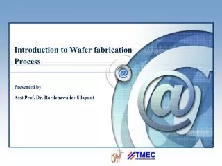
INTRODUCTION to the DESIGN and FABRICATION of IRON-DOMINATED ACCELERATOR MAGNETS. Cherrill Spencer, Magnet Engineer SLAC National Accelerator Laboratory Menlo Park, California, USA Lecture # 1 of 2 Mexican Particle Accelerator School, October 2011. Overview of my Two Lectures, part 1.

E N D
INTRODUCTION to the DESIGN and FABRICATION of IRON-DOMINATED ACCELERATOR MAGNETS Cherrill Spencer, Magnet Engineer SLAC National Accelerator Laboratory Menlo Park, California, USA Lecture # 1 of 2 Mexican Particle Accelerator School, October 2011
Overview of my Two Lectures, part 1 Lecture 1 • Purpose of my lectures on electromagnets • And steps of producing accelerator magnets • How Maxwell’s Equations help us design magnets for particle accelerators • The steps of designing accelerator magnets • Computer modelling to make a detailed design MePAS, Cherrill Spencer, Magnet Lecture #1 Guanajuato. 1st October 2011
Overview of my Two Lectures, part 2 Lecture 2 • Choice of materials and fabrication techniques • Fabricating steel yoke • Fabricating coils • Assembling the whole magnet, connecting it to power and cooling sources • Testing & magnetically measuring a magnet • Installing magnets in a beam line : alignment • Resources where you can find out much more about making accelerator magnets MePAS, Cherrill Spencer, Magnet Lecture #1 Guanajuato. 1st October 2011
Purpose of my lectures; what I cannot do in the time available Why am I smiling? Tell you about designing and fabricating accelerator magnets. What a magnet engineer does in order to produce magnets. Give you an overview of topic, not enough time to go into much detail. Can answer your questions outside of the lecture time. MePAS, Cherrill Spencer, Magnet Lecture #1 Guanajuato. 1st October 2011
Steps in producing accelerator magnets • Accelerator physicist creates a beam lattice, knows purpose of each magnet. Develops set of requirements for each magnet: integrated field strength, aperture size, approximate effective length, how it operates. Gives requirements to a magnet engineer (ME) • ME begins discussions with power supply (PS) specialists and facilities personal re sizes of PS, cooling water, size of tunnel • ME performs the design of each style of magnet, on paper, with computer modeling [more details later] MePAS, Cherrill Spencer, Magnet Lecture #1 Guanajuato. 1st October 2011
More steps in producing accelerator magnets • ME works with a mechanical designer to produce details drawings of all the parts of the magnet • ME continues discussions with PS specialist and facilities personal. Interfaces between magnet and rest of world must be agreed upon: power, water, supports. • ME finds a magnet fabrication vendor; negotiates on choice of materials, cost, schedule • ME monitors fabrication, monitors quality control data, answers questions from vendor • ME supervises magnetic measurements -> field quality • ME discusses magnetic data with AP->can be installed MePAS, Cherrill Spencer, Magnet Lecture #1 Guanajuato. 1st October 2011
Review some electromagnetism facts • Electromagnetism is concerned with the long range interactions between electric charges • Electric interactions occur between static OR moving charges • Magnetic interactions occur only between moving charges • By definition a FIELD is the FORCE created by a system of charges on one unit charge, q=1, having a velocity vector v=1, parallel to the velocity vector of a system of charges. Two fields derived from 2 kinds of force. • electric force coming from the electric field, E • magnetic force coming from the magnetic field, B, according to F = q(E + v x B) MePAS, Cherrill Spencer, Magnet Lecture #1 Guanajuato. 1st October 2011
Electric currents create magnetic fields Compass needle is affected by the bar magnet. It is forced into position: there is a magnetic field produced by the bar magnet. Can draw where lines of force are depending on orientation of the compass needle. Definition: lines of force, also called flux lines, or lines of magnetic induction, go from North to South. These lines have no beginning and no end; North poles and South poles always exist in pairs. MAXWELL’S 2nd EQUATION: ∙B = 0 is math representation of above facts Electric current [positive ions moving] creates a magnetic field around the wire in a plane perpendicular to the wire: lines of force are B. MAXWELL’S 4th EQUATION x B = µ0 J is math representation of this in free space with non-magnetic materials. MePAS, Cherrill Spencer, Magnet Lecture #1 Guanajuato. 1st October 2011
Units. Creating shapely magnetic fields. B is also called the Magnetic Flux Density and its units are Weber/meter2 One Weber/meter2 = one TESLA. We will use Tesla. J is a Current Density: amps/meter2 I can manipulate the current in space into strange shapes and the B flux will have its own shapes. What kind of shape do I want in magnets in a particle accelerator? As I wrote Maxwell’s equations they are partial differential equations, do not yield the B field directly, we have to do some integration with some boundary conditions to be able to calculate values for B. MePAS, Cherrill Spencer, Magnet Lecture #1 Guanajuato. 1st October 2011
What shapes of magnetic fields do accelerator physicists want to guide & focus their beams? Explanation here of LH figure Is a magnetic field pattern for a quadrupole that will focus the beam. Length of arrows indicate strength of field, at that point along an axis. Are not flux lines Can achieve this field shape with just currents but its easier and the currents needed for the same B are smaller if we use some ferromagnetic material to help shape the B MePAS, Cherrill Spencer, Magnet Lecture #1 Guanajuato. 1st October 2011
Representation of electromagnetic fields by potential functions • When dealing with fields, is easier to represent them by POTENTIALS. Can do this with either a vector potential, A or a scalar potential Φ • These potentials are caused by sources such as currents. Pay attention to where the field is relative to the source. • e.g. Electric field intensity derived from Φ through E= -Φ • Similarly, in a region where J=0, B can be derived from the scalar potential [in cartesian coords]: B = -Φ. But also ∙B = 0, so 2Φ=0 (Laplace Eq) MePAS, Cherrill Spencer, Magnet Lecture #1 Guanajuato. 1st October 2011
Equipotential surfaces and ferromagnetism • Metallic surfaces are equipotential surfaces for electric fields, what is the equivalent for magnetic fields? Consider ferromagnetic material such as iron or steel (=iron plus very small percentages of elements such as Carbon, Manganese, Nickel, Sulphur) • Electrons in Fe give an Fe atom a magnetic moment, i.e. it has spin. In a collection of Fe atoms it is energetically favourable for the spins of adjacent atoms to be parallel -> say the domain is magnetized, it has a N and a S pole • But the many domains in a piece of iron are randomly oriented, so overall it has no magnetization. M=0 • If APPLY an external magnetic field then it will make the domains change orientation, piece of iron becomes magnetized. MePAS, Cherrill Spencer, Magnet Lecture #1 Guanajuato. 1st October 2011
Magnetizing a piece of steel • The applied field, usually created by an external excitation current is called H: the magnetic field intensity. Has same units as M: ampere-turns/m • As H is increased so does the M, as domains get larger and rotate to align with H’s direction. Eventually all the domains are parallel to the applied field and SATURATION has been reached. • The overall flux density B is related to H and M: B = µ0(M + H) MePAS, Cherrill Spencer, Magnet Lecture #1 Guanajuato. 1st October 2011
Hysteresis loop : variation of M, B with H Saturation of iron occurs By definition the permeability is ratio between B and H µ = B/H To have a dimensionless parameter put µ = µr µ0 µr is the relative permeability and µ0 is the vacuum perm. It takes all the units! µr =1 for air µr for iron: is not constant varies :1 to ~2000 USE THIS PROPERTY OF IRON IN MAKING MAGNETS MePAS, Cherrill Spencer, Magnet Lecture #1 Guanajuato. 1st October 2011
Consider the magnetic field in the aperture of an accelerator magnet Solve Laplace’s equation by separating variables and imposing boundary conditions that Φ be periodic in the angular coord and be finite at r =0. We know we want our focusing magnet to have 4 fold symmetry.- HOW TO MAKE THIS? 2Φ=0 Series expansion of the scalar potential. Then take negative value of gradient of potential -> field For a given r the m-th term has m maxima and m minima as a function of azimuthal angle . These angular positions may be regarded as the locations of magnetic poles. MePAS, Cherrill Spencer, Magnet Lecture #1 Guanajuato. 1st October 2011
Continue analysis of 2D fields we could produce in a magnet Use De Moivre theorem to get into cartesian coords Study real and imaginary parts and if make phi a constant then that defines an ideal pole shape for a magnet with 2m poles. m=2 gives a quadrupole MePAS, Cherrill Spencer, Magnet Lecture #1 Guanajuato. 1st October 2011
Potentials and field components for 2 D multipoles up to m=5 MePAS, Cherrill Spencer, Magnet Lecture #1 Guanajuato. 1st October 2011
Consider equations in table V= phi Pole shape is a HYPERBOLA with its tip at some radius r MePAS, Cherrill Spencer, Magnet Lecture #1 Guanajuato. 1st October 2011
So a whole quadrupole looks like this The field varies linearly with the the distance from the magnet center. It focuses the beam along one plane while defocusing the beam along the orthogonal plane. An F or focusing quadrupole focuses the particle beam along the horizontal plane MePAS, Cherrill Spencer, Magnet Lecture #1 Guanajuato. 1st October 2011
We have dealt with iron pole shapes, now work out how much current we need x B = µµ0J Maxwell’s 4th equation in differential form x H = J Use H, will be more convenient Apply Stoke’s Theorem and differential form can be written in integral form. Stokes Theorem - The line integral of a potential function around a closed boundary is equal to the area integral of the source distribution within that closed boundary. Suppose the “source” is a simple current Circumference of circle = 2π r MePAS, Cherrill Spencer, Magnet Lecture #1 Guanajuato. 1st October 2011
Use integral of H along flux path to calculate current needed to create B B’, the gradient is constant Consider path 2 Biron ≈B’h, Liron >10h and µiron>1000, so integral along path 2 is ~0.01path1 and can be ignored for estimating current Along Path 1, and Therefore Finally MePAS, Cherrill Spencer, Magnet Lecture #1 Guanajuato. 1st October 2011
Use 2D computer modeling program to define pole and coil shapes, where to place them Define boundaries of steel core and coil in plane at right angles to beam direction. Would be too difficult and tedious to create a pole-tip shape and place some coils near it and calculate by hand the field distribution in the aperture where beam will pass Beam passing here In 1960s family of computer codes called POISSON developed to solve Poisson’s equation and calculate the fields in a combination of steel and coil shapes input by the user. Program makes mesh of small triangles ME inputs material properties and flux boundary conditions into “Automesh” MePAS, Cherrill Spencer, Magnet Lecture #1 Guanajuato. 1st October 2011
Figure showing what POISSON program produces, plus printout of field values TABLE FOR FIELD COEFFICIENTS FOR ATF2 QD0 with 2.5cm rad w/0.25"sideshim SQ end 7 Dec07 NORMALIZATION RADIUS = 2.50000 (BX - I BY) = I * SUM N*(AN + I BN)/R * (Z/R)**(N-1) N N(AN)/R N(BN)/R ABS(N(CN)/R) RATIO 2Npole/4 pole 2 -3.0151E+03 0.0000E+00 3.0151E+03 1.0000E+00 6 -1.7329E+01 0.0000E+00 1.7329E+01 5.7473E-03 10 -1.7196E+02 0.0000E+00 1.7196E+02 5.7033E-02 14 -1.4998E+01 0.0000E+00 1.4998E+01 4.9743E-03 18 4.1147E+00 0.0000E+00 4.1147E+00 1.3647E-03 22 -6.2010E+00 0.0000E+00 6.2010E+00 2.0566E-03 MePAS, Cherrill Spencer, Magnet Lecture #1 Guanajuato. 1st October 2011
Typical set of magnet requirements from AP For A DIPOLE MAGNET • Nominal bending angle Theta = 97.2434 mrad • Nominal integral dipole field at 9 GeV B0L = 29.193 kG-m • Effective length (approx value) L = 1.800 m • Height of aperture 25.4 mm • Operating field range from 15.5 to 16.6 kG • Integrated strength operating range 27.90 to 29.88 kG-m • Minimum full pole width for beam 210 mm • Dipole field variation relative to average dipole field in four bends in e- or e+ chicane • DeltaB0/Baver = +/-0.1% • Multipole field tolerances at R = 10 cm (for “coupled” beams) • B1/B0 = +/-0.21% (quadrupole) • B2/B0 = +/-0.27% (sextupole) • B3/B0 = +/-0.30% (octupole) • B4/B0 = +/-0.33% (decapole) MePAS, Cherrill Spencer, Magnet Lecture #1 Guanajuato. 1st October 2011
Shape of top right hand part of new sector 10 dipole: my design in response to the requirements given to me by an AP Total width of core: 30” [76.2cm] Main coil: 20 turns of 0.44”sq hollow copper conductor with 0.186” hole Trim coil: 88 turns of AWG#10 solid copper wire: <5% of main coil Low carbon solid steel core Total width of poletip at gap is 26.0 cm Low carbon steel core Need model only one quarter of the whole magnet 1.27cm (0.5”) half-gap 2.54cm (1”) wide, 30º chamfer improves the multipoles in the gap to well below the specs MePAS, Cherrill Spencer, Magnet Lecture #1 Guanajuato. 1st October 2011
POISSON 2D MODEL of new style dipole showing magnetic flux lines, with trim working In POISSON, because of symmetry of top and bottom halves and left and right halves, need to model only one quarter of the whole magnet Note the flux lines are perpendicular to the mid-plane of the gap where beam will pass [into the page] and enter the steel core at right angles to edge of steel MePAS, Cherrill Spencer, Magnet Lecture #1 Guanajuato. 1st October 2011
Magnet Lecture #1 Homework Question 0.30m Develop an equation that connects the path integral of B through this section of a dipole and the total current in the section of the coil enclosed by the path. If the half gap is 0.025m and B is to be one Tesla, what is the value of NI needed 0.17m 0.025m MePAS, Cherrill Spencer, Magnet Lecture #1 Guanajuato. 1st October 2011
Photo of a dipole with “dog-ear” coils MePAS, Cherrill Spencer, Magnet Lecture #1 Guanajuato. 1st October 2011