Download
1 / 27
270 likes | 428 Views
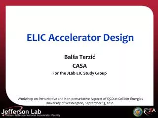
Introduction to the Accelerator and Design. Geoffrey Krafft CASA For the JLab EIC Study Group MEIC “Friendly” Review, September 15-16, 2010. Outline. Introduction to the MEIC Machine Design Some Details Recent Highlights Summary. ELIC : JLAB’s Future Nuclear Science Program.

E N D
Introduction to the Accelerator and Design Geoffrey Krafft CASA For the JLab EIC Study Group MEIC “Friendly” Review, September 15-16, 2010
Outline • Introduction to the MEIC • Machine Design • Some Details • Recent Highlights • Summary
ELIC: JLAB’sFuture Nuclear Science Program • JLab has been developing a design of an electron-ion collider (ELIC) based on the CEBAF recirculating SRF linac for nearly a decade. • Requirements of the future nuclear science program drives ELIC design efforts to focus on achieving • ultra high luminosity per detector (up to 1035 at high energy) in multiple detectors • very high polarization (>80%) for both electrons & light ions • The focus of this review will be on the Medium-energy Electron Ion Collider ( ) project. • We’ve found such a stage to be a good compromise between science, technology and project cost • Energy range is up to 60 GeV ions and 11 GeV electrons • A well-defined upgrade capability to higher energies is maintained • High luminosity & high polarization continue to be the design drivers
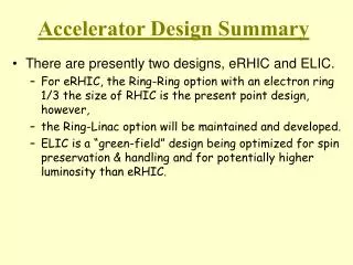
Collider Luminosity • Probability an event is generated by a Beam 1 bunch with Gaussian density crossing a Beam 2 bunch with Gaussian transverse density • Event rate with equal transverse beam sizes • Linear beam-beam tune shift
Luminosity beam-beam tune-shift relationship • Express Luminosity in terms of the (larger!) vertical tune shift (i either 1 or 2) • Necessary, but not sufficient, for self-consistent design • Expressed in this way, and given a “known” limit to the beam-beam tune shift, the only variables to manipulate to increase luminosity are the stored current, the aspect ratio, and the β* (beta function value at the interaction point) • Applies to ERL-ring colliders, stored beam (ions) only
Evolutionof the ELIC Design • Energy Recovery Linac – Storage Ring (ERL-R) • ERL with Circulator Ring – Storage Ring (CR-R) • Back to Ring-Ring (R-R) – by taking advantage of CEBAF as full energy polarized injector • Challenge: high current polarized electron source • ERL-Ring: 2.5 A • Circulator ring: 20 mA • State-of-art: 0.1 mA • 12 GeV CEBAF Upgrade polarized source/injector already meets beam requirement of ring-ring design • CEBAF-based R-R design preserves high luminosity and high polarization (+polarized positrons…)
MEIC : Medium Energy EIC medium-energy IPs polarimetry low-energy IP • Three compact rings: • 3 to 11 GeV electron • Up to 12 GeV/c proton (warm) • Up to 60 GeV/c proton (cold)
MEIC : Detailed Layout warm ring cold ring
ELIC: High Energy & Staging Straight section Serves as a large booster to the full energy collider ring Arc
Ring-Ring Design Features • Ultra high luminosity • Polarized electrons and polarized light ions • Up to three IPs (detectors) for high science productivity • “Figure-8” ion and lepton storage rings • Ensures spin preservation and ease of spin manipulation • Avoids energy-dependent spin sensitivity for all species • Present CEBAF injector meets MEIC requirements • 12 GeV CEBAF can serve as a full energy injector • Simultaneous operation of collider & CEBAF fixed target program possible • Experiments with polarized positron beam would be possible
Figure-8 Ion Rings • Figure-8 optimum for polarized ion beams • Simple solution to preserve full ion polarization by avoiding spin resonances during acceleration • Energy independence of spin tune • g-2 is small for deuterons; a figure-8 ring is the only practical way to arrange for longitudinal spin polarization at interaction point • Transverse polarization for deuteron looks feasible • Long straights can be useful • Allows multiple interactions in the same straight – can help with chromatic correction • Only disadvantage is relatively small cost increase
Short Term Design “Contract” MEIC accelerator team is committed to completing a MEIC design within by the next International Advisory Committee Meeting with the following features • CM energy up to 51 GeV, up to 11 GeV electron, 60 (30) GeV proton (ion) • Upgrade option to high energy • Three IPs, at least two of them are available for medium energy collisions • Luminosity up to of order 1034 cm-2 s-1per collision point • Fullacceptance for at least one medium-energy detector • High polarization for both electron and light ion beams This “contract” will be renewable every 6 months with major revision of design specifications allowed due to development of • Nuclear science program • Accelerator R&D
Short Term Technical Strategy • Focus of MEIC accelerator team during this period is to work out a complete machine design with sufficient technical detail. • We are taking a conservative technical position by limiting many MEIC design parameters within or close to the present state-of-art in order to minimize technical uncertainty. • Maximum peak field of ion superconducting dipole is 6 T • Maximum synchrotron radiation power density is 20 kW/m • Maximum betatron value at FF quad is 2.5 km • This conservative technical design will form a baseline for future design optimization guided by • Evolution of the science program • Technology innovation and R&D advances.
Adopts Proven Luminosity Approaches High luminosity at B factories comes from • Very small β* (~6 mm) to reach very small spot sizes at collision points • Very short bunch length (σz~ β*) to avoid hour-glass effect • Very small bunch charge which makes very short bunch possible • High bunch repetition rate restores high average current and luminosity • Synchrotron radiation damping KEK-B and PEPII already over2x1034/cm2/s JLab believes these ideas should be replicated in the next electron-ion collider
MEIC & ELIC: Luminosity Vs. CM Energy e + p facilities e + A facilities https://eic.jlab.org/wiki/index.php/Machine_designs
Electron Figure-8 Collider Ring Spin Rotator (8.8°/4.4°, 50 m) Injection from CEBAF Potential 3rd IR (60 m) 1/4 Electron Arc (106.8°, 117.5 m) Spin Rotator (8.8°/4.4°, 50 m) polarimetry Figure-8 crossing angle: 2x30° RF Straight (20 m) Experimental Hall (radius 15 m) 1/4 Electron Arc (106.8°, 117.5 m) IR(60 m) IR(60 m) Spin Rotator (8.8°/4.4°, 50 m) Spin Rotator (8.8°/4.4°, 50 m)
Electron Collider Ring • Electron ring is designed in a modular way • two long (140 m) straights (for two IPs) • two short (20 m) straights (for RF module), dispersion free • four identical (106.8º) quarter arcs, made of 135º phase advance FODO cell with dispersion suppressing • four 50 m long electron spin rotator blocks One quarter arc 135º FODO Cell for arc 2 dis. sup. cells 2 dis. sup. cells 26 FODO cells circumference ~1000 m phase adv/cell: 1350
Electron Polarization in Figure-8 Ring electron spin in vertical direction ions electron electron spin in vertical direction Universal Spin Rotators electron spin in longitudinal direction Self polarization time in MEIC spin tuning solenoid • Polarized electron beam is injected at full energy from 12 GeV CEBAF • Electron spin is in vertical direction in the figure-8 ring, taking advantage of self-polarization effect • Spin rotators will rotate spin to longitudinal direction for collision at IP, than back to vertical direction in the other half of the ring
Universal Spin Rotator e- spin from arc spin 8.8º BL = 28.712 Tesla m 4.4º solenoid 4.16 m solenoid 4.16 m decoupling quad insert C 0 M = - C 0
Beam Synchronization • Electron speed is already speed of light at 3 to 11 GeV, ion speed is not, there is 0.3% variation of ion speed from 20 to 60 GeV • Needs over 67 cm path length change for a 1000 m ring • Solution for case of two IPs on two separate straights • At the higher energies (close to 60 GeV), change ion path length ion arc on movers • At the lower energies (close to 20 GeV), change bunch harmonic number Varying number of ion bunches in the ring • With two IPs in a same straights Cross-phasing • More studies/implementation scheme needed Harmonic Number vs. Proton Energy eRHIC e-Ring Path Length Adjustment (eRHIC Ring-Ring Design Report)
Highlights of Recent Design Activities • Continuing design optimization • Tuning main machine parameters to better serve the science program • Now aim for high luminosity AND large detector acceptance • Simplified design and reduced R&D requirements • Focused on detailed design of major components • Completed baseline design of two collider rings • Completed 1st design of Figure-8 pre-booster (B Erdelyi, Today) • Completed beam polarization scheme with universal electron spin rotators (P. Chevtsov, Morozov Today) • Updated IR optics design (A. Bogacz, Tomorrow) • Continued work on critical R&D • Beam-beam simulations (B.Terzic, Tomorrow) • Nonlinear beam dynamics and instabilities(B. Yunn, Today, Zhang) • Chromatic corrections (V. Morozov, Tomorrow)
ELIC Study Group A. Accardi, A. Afanasev, A. Bogacz, J. Benesch, P. Brindza, A. Bruell, L. Cardman, Y. Chao, S. Chattopadhyay, J.P. Chen, E. Chudakov, P. Degtiarenko, J. Delayen, Ya. Derbenev, R. Ent, P. Evtushenko, A. Freyberger, D. Gaskell, J. Grames, V. Guzey, L. Harwood, T. Horn, A. Hutton, C. Hyde, N. Kalantarians, R. Kazimi, F. Klein, G. A. Krafft, R. Li, F. Marhauser, L. Merminga, V. Morozov, J. Musson, P. Nadel-Turonski, F. Pilat, M. Poelker, A. Prokudin, R. Rimmer, H. Sayed, M. Spata, A. Thomas, M. Tiefenback, B. Terzić, H. Wang, C. Weiss, B. Wojtsekhowski, B. Yunn, Y. Zhang - Jefferson Laboratory staff and users M. Sullivan - SLAC W. Fischer, C. Montag - Brookhaven National Laboratory D. Barber - DESY V. Danilov - Oak Ridge National Laboratory P. Ostroumov - Argonne National Laboratory B. Erdelyi - Northern Illinois University and Argonne National Laboratory V. Derenchuk - Indiana University Cyclotron Facility A. Belov - Institute of Nuclear Research, Moscow, Russia V. Dudnikov, R. Johnson - Muons Inc. A. Kondratenko - Novosibirsk
Summary • MEIC is optimized to collide a wide variety of polarized light ions and unpolarized heavy ions with polarized electrons (or positrons) • MEIC covers an energy range matched to the science program proposed by the JLab nuclear physics community (~2500 GeV2) with luminosity up to 6x1033 cm-2s-1 • An upgrade path to higher energies (250x10 GeV2), has been developed which should provide luminosity of 1x1035 cm-2s-1 • The design is based on a Figure-8 ring for optimum polarization, and an ion beam with high repetition rate, small emittance and short bunch length • Electron cooling is absolutely essential for cooling and bunching the ion beams • We have identified the critical accelerator R&D topics for MEIC, and hope to start working on them more deeply soon MEIC is the future of Nuclear Physics at Jefferson Lab