Download
1 / 15
210 likes | 530 Views
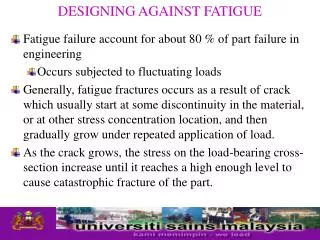
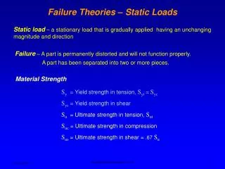
Failure – A part is permanently distorted and will not function properly. A part has been separated into two or more pieces. Material Strength. S y = Yield strength in tension, S yt = S yc. S ys = Yield strength in shear. S u = Ultimate strength in tension, S ut.

E N D
Failure – A part is permanently distorted and will not function properly. A part has been separated into two or more pieces. Material Strength Sy = Yield strength in tension, Syt = Syc Sys = Yield strength in shear Su = Ultimate strength in tension, Sut Suc = Ultimate strength in compression Sus = Ultimate strength in shear = .67Su Failure Theories – Static Loads Static load – a stationary load that is gradually applied having an unchanging magnitude and direction Mechanical Engineering Dept., SJSU
Brittle material yields very little before fracturing, the yield strength is approximately the same as the ultimate strength in tension. The ultimate strength in compression is much larger than the ultimate strength in tension. Ductile and Brittle Materials A ductile material deforms significantly before fracturing. Ductility is measured by % elongation at the fracture point. Materials with 5% or more elongation are considered ductile. Mechanical Engineering Dept., SJSU
(max)component > ()obtained from a tension test at the yield point Failure = Sy Sy Sy = To avoid failure 2 2 (max)component < = Sy Sy max = n = Safety factor 2 n Design equation =Sy Failure Theories – Ductile Materials Yield strength of a material is used to design components made of ductile material • Maximum shear stress theory (Tresca 1886) Mechanical Engineering Dept., SJSU
Simple tension test → (Sy)t Hydrostatic state of stress → (Sy)h t (Sy)h (Sy)t >> Distortion contributes to failure much more than change in volume. h t h h Failure Theories – Ductile Materials • Distortion energy theory (von Mises-Hencky) (total strain energy) – (strain energy due to hydrostatic stress) = strain energy due to angular distortion > strain energy obtained from a tension test at the yield point → failure Mechanical Engineering Dept., SJSU
3 1 3 2 1 E E E E E 3D case UT = ½1ε1+½2ε2+½3ε3 Stress-strain relationship 2 1 v ε1 = E E 2 v v v ε2 = E 1 3 2E v v ε3 = E UT = (12+22+32) - 2v (12 + 13 + 23) Failure Theories – Ductile Materials The area under the curve in the elastic region is called the Elastic Strain Energy. U = ½ ε Strain energy Mechanical Engineering Dept., SJSU
(1) Substitute 1=2=3 = h Simplify and substitute 1+2+3= 3hinto the above equation (1+2+3)2 3h2 (1–2v) Uh = (1–2v) = 2E 6E 1 1 2E 2E Subtract the hydrostatic strain energy from the total energy to obtain the distortion energy 1 + v (2 –3)2 (1 –3)2+ (1 –2)2+ Ud= UT – Uh = 6E Uh = (h2+h2+h2) - 2v (hh + hh+ hh) UT = (12+22+32) - 2v (12 + 13 + 23) Failure Theories – Ductile Materials Distortion strain energy = total strain energy – hydrostatic strain energy Ud = UT – Uh (2) Mechanical Engineering Dept., SJSU
(2 –3)2 (1 –3)2+ ½ (1 –2)2+ < Sy 1 + v (Sy)2 Utest = 2 3E 1 + v (2 –3)2 (1 –3)2+ (1 –2)2+ Ud= UT – Uh = 6E Failure Theories – Ductile Materials Strain energy from a tension test at the yield point 1=Syand 2=3= 0 Substitute in equation (2) (2) To avoid failure, Ud < Utest Mechanical Engineering Dept., SJSU
Sy ′ = n (2 –3)2 (1 –3)2+ ½ (1 –2)2+ < Sy 2 2D case, 3=0 ½ (12–12+22) < Sy = Where is von Mises stress Design equation Failure Theories – Ductile Materials Mechanical Engineering Dept., SJSU
32=Sy2 Sys=Sy/ √3 → Sys = .577 Sy Relationship between yield strength in tension and shear If y = 0, then the design equation can be written in terms of the dominant component stresses (due to bending and torsion) 1, 2= x/2 ± [(x)/2]2 + (xy)2 Sy 1/2 (x)2+ 3(xy)2= n Failure Theories – Ductile Materials Pure torsion, = 1= – 2 (12– 2 1+22) = Sy2 Mechanical Engineering Dept., SJSU
Sy ′ = n Sy , Su • Select material: consider environment, density, availability → n Size Weight Cost Sy max = 2n Design Process Distortion energy theory Maximum shear stress theory • Choose a safety factor The selection of an appropriate safety factor should be based on the following: • Degree of uncertainty about loading (type, magnitude and direction) • Degree of uncertainty about material strength • Uncertainties related to stress analysis • Consequence of failure; human safety and economics • Type of manufacturing process • Codes and standards Mechanical Engineering Dept., SJSU
Design Process • Use n = 1.2 to 1.5 for reliable materials subjected to loads that can be determined with certainty. • Use n = 1.5 to 2.5 for average materials subjected to loads that can be determined. Also, human safety and economics are not an issue. • Use n = 3.0 to 4.0 for well known materials subjected to uncertain loads. Mechanical Engineering Dept., SJSU
Sy ′= n Sy , Su • Select material, consider environment, density, availability → • Use appropriate failure theory to calculate the size. Sy max = 2n Design Process • Choose a safety factor • Formulate the von Mises or maximum shear stress in terms of size. • Optimize for weight, size, or cost. Mechanical Engineering Dept., SJSU
Suc >> Sut Suc 3 1 Sut Stress state Tension test Compression test Failure envelope The component is safe if the state of stress falls inside the failure envelope. 1 > 3 and2 = 0 Failure Theories – Brittle Materials One of the characteristics of a brittle material is that the ultimate strength in compression is much larger than ultimate strength in tension. Mohr’s circles for compression and tension tests. Mechanical Engineering Dept., SJSU
3 or2 Sut Sut I Safe Safe Sut Sut 1 Suc Safe II -Sut -Sut Safe III Suc Suc Cast iron data Three design zones Failure Theories – Brittle Materials Modified Coulomb-Mohr theory 3 or2 1 Mechanical Engineering Dept., SJSU
2>0 and 1> 2 1>0 , Sut Design equation 1= n Zone II 2<0 and 2<Sut 1>0 , Sut 1= Design equation n Zone III 2 1 1 1 2<0 and 2>Sut 1( 1>0 , – – ) = n Sut Suc Suc Design equation Failure Theories – Brittle Materials 3 Zone I Sut I Sut 1 II -Sut III Suc Mechanical Engineering Dept., SJSU