Download
1 / 19
190 likes | 290 Views
Explore the shift towards new logic devices due to the limitations of CMOS technology, including QCA, CNT, and SET applications. Discover synthesis techniques and challenges in integrating new logic devices for enhanced computational capabilities.

E N D
Emerging Logic Devices An introduction to new computing paradigms (for EEL-4705 Fall 2006)
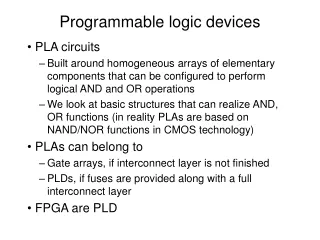
Why change to new logic devices? • Currently all logic gates fabricated using CMOS • With the current rate of scaling CMOS technology is set to hit a roadblock (in next 8-10 years) where it cannot be further scaled down. • Scaling enables to pack more and more computing power in each new generation of ICs. • To keep scaling further down we’ll need to adopt other nanotech devices to perform computation and which can be scaled to a level way beyond what CMOS can. • Each new emerging nanotechnology uses a particular technique to represent and manipulate data (like transistor in CMOS) • Hence each new type of nanotechnology uses different logic devices to design circuits in a way to maximize their performance (Similar to NAND/NOR logic being currently used in CMOS).
P = +1 P = - 1 Some of the Promising Technologies… • Quantum-Dot Cellular Automata (QCA) • Carbon Nanotubes (CNT) • Single Electron Transistor (SET)
CNT Transistor (Same logic as CMOS) SET Minority Gate (Uses Minority and Inverter logic) CNT and SET Logic Rui Zhang, Pallav Gupta, and Niraj K. Jha. "Synthesis of Majority and Minority Networks and Its Applications to QCA, TPL and SET Based Nanotechnologies," in Proc. Int. Conf. VLSI Design, pp. 229-234, Jan. 2005
QCA Majority Gate QCA OR Gate QCA AND Gate QCA Inverter QCA NAND Gate QCA Logic
QCA Logic Propagation Stable Unstable Stable Stable Unstable Unstable Stable
QCA Logic Propagation 1 Unstable Stable Unstable Unstable 1 Inverter Chain
Wire Crossbar 1 1
QCA layout of Adder-1 QCA Logic – Single Bit Adder
Next Big Challenge… • Fine… We develop the new technology that will help us keep up with the scaling and hence enhancing our computational capabilities… • What next? • What about the millions of logic circuits and designs? How will they be incorporated in this new technology? • In the next slide we give an example of how to synthesize any Boolean logic function (AND/OR logic) into a Majority logic function. • We also need to make sure that the new Majority Logic function is the best possible solution in terms of number of logic gates (majority gates in case of QCA). • K-map based majority Logic Synthesis is used to derive the best solution.
Multilevel Majority Network Synthesis All positive unate functions that can be realized by a three-input majority gate and their corresponding admissible patterns on the K-map. There is a library of 38 such three-input functions. Rui Zhang, Pallav Gupta, and Niraj K. Jha. "Synthesis of Majority and Minority Networks and Its Applications to QCA, TPL and SET Based Nanotechnologies," in Proc. Int. Conf. VLSI Design, pp. 229-234, Jan. 2005
Multilevel Majority Network Synthesis • This method is used to derive a majority-gate based network (circuit) from an algebraically factored, multi output combinational network (circuit) • It goes this way… First, we need to make sure that no function (n) in the network has more than three input variables. • Next, K-map based majority logic synthesis is used on each reduced function (n) to represent that function in terms of three-majority gates. • Using this technique, it has been proven that any three-input node function (AND/OR function) can be represented using a maximum of four majority gates.
AND/OR Mapping • Used for small and simple functions that can be represented by directly mapping AND/OR gates as majority gates. • Example 1 • If a node (function n) requires fewer than or equal to four majority gates by AND/OR mapping, there is no need to spend time to represent it using K-map based method. • Example 2 _ x2 f1 x1 f1 0 0 x1 n x2 n _ x2 1 _ x1 1 0 0 f2 f2 x3 x3 Using a K-map based method would have resulted in four majority gates x1 f1 1 n 0 x3 _ x2
K-map based Majority Synthesis 0 0 • Example 1: 0 0 0 0 0 • Has to be broken into n = M (f1,f2,f3) • Find an admissible pattern for f1 • For finding f2, set Ψ1 is obtained as follows: if a minterm of n is not a minterm of f1, add this minterm to Ψ 1. • Similarly, for finding f2, set Ψ 0 is obtained as follows: if a maxterm of n is not a maxterm of f1, add this maxterm to Ψ 0. • A suitable pattern for f2 is then determined using new Ψ1 and Ψ 0. • Furthermore, to determine f3, Ψ1 and Ψ 0 are updated again as follows: if a minterm (maxterm) of node n is not a minterm (maxterm) of both f1 and f2, add this minterm (maxterm) to Ψ1 (Ψ 0 ). • AND/OR mapping would have required eight majority gates. 0 0 0 0
K-map based Majority Synthesis (Cont…) 0 0 • Example 2: 0 0 0 0 0 0 • Has to be broken into n = M (f1,f2,f3) • Find an admissible pattern for f1 • For finding f2, set Ψ1 is obtained as follows: if a minterm of n is not a minterm of f1, add this minterm to Ψ 1. • Similarly, for finding f2, set Ψ 0 is obtained as follows: if a maxterm of n is not a maxterm of f1, add this maxterm to Ψ 0. • A suitable pattern for f2 is then determined using new Ψ1 and Ψ 0. • Furthermore, to determine f3, Ψ1 and Ψ 0 are updated again as follows: if a minterm (maxterm) of node n is not a minterm (maxterm) of both f1 and f2, add this minterm (maxterm) to Ψ1 (Ψ 0 ). • AND/OR mapping would have required eleven majority gates. 0 0 0 0 0 0 0 0
Conclusion… • We learnt about the Emerging nanotech devices that might be used in future. • We learnt that different technologies use different logic styles. • We saw how we can relate Majority Logic with present day AND/OR logic. • We also studied an algorithm to convert present day circuits (AND/OR logic) into Majority gate logic circuits using K-map based synthesis method.