Download
1 / 57
590 likes | 805 Views
ECE 558/658 : Lecture 20 Interconnect Design (Chapter 9) Clock distribution (Chapter 10.3.3). Atul Maheshwari. The Wire – Chapter 4 – Lecture 15. schematics. physical. Capacitance: The Parallel Plate Model. Fringing Capacitance. Complete Capacitance Picture. Wire Resistance .

E N D
ECE 558/658 : Lecture 20Interconnect Design(Chapter 9)Clock distribution(Chapter 10.3.3) Atul Maheshwari
The Wire – Chapter 4 – Lecture 15 schematics physical
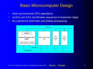
Impact of Interconnect Parasitics Classes of Parasitics • Capacitive • Resistive • Inductive Impact of Parasitics • • Affect Performance • Increase delay • Increase power dissipation • Reduce Robustness
INTERCONNECT Dealing with Capacitance
Capacitive Cross TalkDynamic Node V DD CLK C XY Y C Y In 1 X In PDN 2 2.5 V In 3 0 V CLK 3 x 1 mm overlap: 0.19 V disturbance
Capacitive Cross TalkDriven Node 0.5 0.45 0.4 tr↑ X 0.35 C R XY 0.3 Y V Y tXY = RY(CXY+CY) X 0.25 C Y 0.2 V (Volt) 0.15 0.1 0.05 0 0 0.2 0.4 0.6 0.8 1 t (nsec) Keep time-constant smaller than rise time
Dealing with Capacitive Cross Talk • Avoid floating nodes • Protect sensitive nodes • Make rise and fall times as large as possible • Differential signaling • Do not run wires together for a long distance • Use shielding wires • Use shielding layers
Shielding Shielding wire GND Shielding V DD layer GND Substrate ( GND )
Cross Talk and Performance -When neighboring lines switch in opposite direction of victim line, delay increases DELAY DEPENDENT UPON ACTIVITY IN NEIGHBORING WIRES Cc Miller Effect - Both terminals of capacitor are switched in opposite directions (0 Vdd, Vdd 0) - Effective voltage is doubled and additional charge is needed (from Q=CV)
Impact of Cross Talk on Delay r is ratio between capacitance to GND and to neighbor
Structured Predictable Interconnect • Example: Dense Wire Fabric ([Sunil Kathri]) • Trade-off: • Cross-coupling capacitance 40x lower, 2% delay variation • Increase in area and overall capacitance
Encoding Data Avoids Worst-CaseConditions In Encoder Bus Decoder Out
V DD V V in out C L Driving Large Capacitances • Transistor Sizing • Cascaded Buffers
Using Cascaded Buffers In Out CL = 20 pF 1 2 N 0.25 mm process Cin =2.5 fF tp0 = 30 ps F = CL/Cin = 8000 fopt = 3.6 N = 7 tp = 0.76 ns (See Chapter 5)
How to Design Large Transistors D(rain) Reduces diffusion capacitance Reduces gate resistance Multiple Contacts S(ource) G(ate) small transistors in parallel
Bonding Pad Design Bonding Pad GND 100 mm Out VDD Out In GND
V DD V DD En Out En En Out In In En Increased output drive Out = In.En + Z.En Tristate Buffers
INTERCONNECT Dealing with Resistance
Impact of Resistance • Impact on performance - We have already learned how to drive RC interconnect • Impact of resistance is commonly seen in power supply distribution: • IR drop • Voltage variations • Power supply is distributed to minimize the IR drop and the change in current due to switching of gates
Using Bypasses Driver WL Polysilicon word line Metal word line Driving a word line from both sides Metal bypass WL K cells Polysilicon word line Using a metal bypass
The distributed rc-line Tr RN-1 RN R1 R2 C1 C2 CN-1 CN Vin Resistivity and Performance Diffused signal propagation Delay ~ RC Delay ~ L2
Repeaters • Repeaters are buffers / inverters inserted at regular intervals. • Makes Delay linearly proportional to the wire length. • Questions to be answered – Where and how big the repeaters should be ?
Reducing RC-delay – Repeater insertion Repeater (chapter 5)
Repeater Insertion Taking the repeater loading into account For a given technology and a given interconnect layer, there exists an optimal length of the wire segments between repeaters. The delay of these wire segments is independent of the routing layer!
Repeater Design Limitations • Delay-optimal repeaters are area and power hungry – use of sub-optimal insertion • Optimal placement requires accurate modeling of interconnect. • Optimal placement not always possible. • Performance limited due to significant interconnect resistance. • Source of noise – Supply and Substrate
Advanced techniques - Reducing the swing • Reducing the swing potentially yields linear reduction in delay • Also results in reduction in power dissipation • Delay penalty is paid by the receiver • Requires use of “sense amplifier” to restore signal level • Frequently designed differentially (e.g. LVDS)
VDD VDD VDD VDD L Out Out VDD L In C L driver receiver Single-Ended Static Driver and Receiver
V V DD DD M M f 2 4 Bus Out C C out bus In . M In . M f f 1 3 1 2 2.5 V 2 asym V bus V sym 1.5 f 1 0.5 0 0 2 4 6 8 10 12 time (ns) Dynamic Reduced Swing Network V(Volt)
RI Introduced Noise V I DD f ` V V - pre ` DD R X I V M 1 V R
Power Distribution • Low-level distribution is in Metal 1 • Power has to be ‘strapped’ in higher layers of metal. • The spacing is set by IR drop, electromigration, inductive effects • Always use multiple contacts on straps
3 Metal Layer Approach (EV4) 3rd “coarse and thick” metal layer added to the technology for EV4 design Power supplied from two sides of the die via 3rd metal layer 2nd metal layer used to form power grid 90% of 3rd metal layer used for power/clock routing Metal 3 Metal 2 Metal 1 Courtesy Compaq
4 Metal Layers Approach (EV5) 4th “coarse and thick” metal layer added to the technology for EV5 design Power supplied from four sides of the die Grid strapping done all in coarse metal 90% of 3rd and 4th metals used for power/clock routing Metal 4 Metal 3 Metal 2 Metal 1 Courtesy Compaq
6 Metal Layer Approach – EV6 2 reference plane metal layers added to the technology for EV6 design Solid planes dedicated to Vdd/Vss Significantly lowers resistance of grid Lowers on-chip inductance RP2/Vdd Metal 4 Metal 3 RP1/Vss Metal 2 Metal 1 Courtesy Compaq
Interconnect Projections:Geometry • # of metal layers is steadily increasing due to: • Increasing die size and device count: we need more wires and longer wires to connect everything • Rising need for a hierarchical wiring network; local wires with high density and global wires with low RC 0.25 mm wiring stack
e Interconnect Projections :Low-k dielectrics • Both delay and power are reduced by dropping interconnect capacitance • Types of low-k materials include: inorganic (SiO2), organic (Polyimides) and aerogels (ultra low-k) • The numbers below are on the conservative side of the NRTS roadmap
Interconnect Projections: Copper • Copper is planned in full sub-0.25 mm process flows and large-scale designs (IBM, Motorola, IEDM97) • With cladding and other effects, Cu ~ 2.2 mW-cm vs. 3.5 for Al(Cu) 40% reduction in resistance • Electromigration improvement; 100X longer lifetime (IBM, IEDM97) • Electromigration is a limiting factor beyond 0.18 mm if Al is used (HP, IEDM95) Vias
Diagonal Wiring destination diagonal y source x Manhattan • 20+% Interconnect length reduction • Clock speed Signal integrity Power integrity • 15+% Smaller chips plus 30+% via reduction Courtesy Cadence X-initiative
Clock Distribution H-tree Clock is distributed in a tree-like fashion
More realistic H-tree [Restle98]
The Grid System • No rc-matching • Large power