Download
1 / 51
510 likes | 719 Views
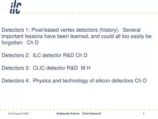
Detectors 1: Pixel-based vertex detectors (history ). Several important lessons have been learned, and could all too easily be forgotten. Ch D Detectors 2: ILC detector R&D Ch D Detectors 3: CLIC detector R&D M H Detectors 4: Physics and technology of silicon detectors Ch D.

E N D
Detectors 1: Pixel-based vertex detectors (history). Several important lessons have been learned, and could all too easily be forgotten. Ch D Detectors 2: ILC detector R&D Ch D Detectors 3: CLIC detector R&D M H Detectors 4: Physics and technology of silicon detectors Ch D Ambleside School Chris Damerell
Pixel-based vertex detectors – history(as seen through one pair of eyes) Chris Damerell (RAL) All such detectors to date, that have been completed and worked, (only three in fact) have been built by just one evolving detector collaboration. However, very many institutes have participated over the past 30 years … There are many new detectors of this type in the pipeline, for ATLAS, CMS. ALICE, STAR, SuperBelle, SuperB, …so the story will become more complex Ambleside School Chris Damerell
Participating institutions which have made MAJOR contributions: • Birmingham U RAL • Bristol U SLAC • Brunel U Tohoku U • CERN UCSB • Colorado State U UCSC • Edinburgh U U of Washington • Lancaster U U of Wisconsin • Liverpool U Yale U • U of Massachusetts andour friends at e2V Technologies • MIT • MPI Munich • Nagoya U • Nijmegen U • Oregon U • Oxford U • Some of the ‘minor’ contributions (eg Gary Feldman from Harvard U, Ulie Koetz frm MPI) were nevertheless of critical importance. Each individual (>>100) could give a different and in some respects more accurate presentation of this complex story … Ambleside School Chris Damerell
Test of the ‘complete theory of particle physics’ • Ch D (post-doc) to Rutherford Lab Scientific Programme Sub-Committee, 2 Feb 1970 • Physics motivation: to build a focusing spectrometer (pioneered by Dave Ritson and Karl Brown at Fermilab) for the SPS, then under construction, with sufficient momentum resolution to make definitive tests of the Bootstrap Theory of Strong Interactions (claimed at the time to be the complete theory of particle physics) • By 1974, there were growing doubts about the bootstrap theory. Furthermore it was clear that we could not muster the necessary resources, so we teamed up with the CERN-Munich Group and a more modest goal: to ‘think what we could do with their existing PS spectrometer’ • All thoughts of high-precision tracking detectors were shelved, for the time being … • Thus ACCMOR, one of the most productive collaborations in particle physics, was born • Meanwhile, events elsewhere (Bell Labs and SLAC) were shaping our future Ambleside School Chris Damerell
Invention of the charge-coupled device (CCD) • Bell Syst Tech J, 49 (1970) 49 • Bell Syst Tech J, 49 (1970) 593 Ambleside School Chris Damerell
Boyle and Smith having fun at Bell Labs, 1974 • but all this passed without notice by the particle physics community Ambleside School Chris Damerell
The discovery of charm • SPEAR, an ‘unfunded’ unfashionable minor project, built on a parking lot, started running in 1973 • Kjell Johnsen’s visit to SLAC • Purpose? “Measure one number (R) then switch it off” • But the first measurements of R at high energies (above 3 GeV) were unexpectedly a bit too high ... Ambleside School Chris Damerell
ICHEP London July 1974 • Burt Richter skipped the ‘boring’ sessions on resonance physics • In his talk, he described the anomalies in experimental measurement of R, and John Ellis summarised over 20 possible theoretical interpretations • Returning to SLAC, some of Burt’s colleagues convinced the group to perform a scan at reduced energies Ambleside School Chris Damerell
The ‘November Revolution’ on 10th November 1974 was followed by the Nobel Prize to Richter and Ting in 1976 Ambleside School Chris Damerell
PS Committee, Mon Nov 11th 1974. After an hour of theoretical discourse: “Ladies and gentlemen, I have no idea what this discovery means, but it’s a disaster for charm” • What had in fact been found was the ground state of charmonium, and the subsequently discovered spectrum satisfied perfectly the expectations of the non-relativistic quark model.The bootstrap theory was dead and buried and Dick Dalitzwho had lost 2/3 of his audience at the 1965 ICHEP conference, was in great demand at last! 9.5 GeV 3 GeV Look at the masses, remembering that the baryon resonances had completely run out by ~2 GeV. This was extremely unexpected. The upsilon (b-bbar) was discovered in 1977, but the top quark, at 175 GeV, was tough (found in 1994 at the Tevatron, Fermilab), though in 1984 it had been claimed at 60 GeV (UA1) Ambleside School Chris Damerell
ISR startup, Jan1971 • ‘The ISR was beginning its reputation as the most perfect machine in high energy physics ever built’ • So why didn’t it discover charm? • Charmonium was being produced in abundance, but being unexpected,nobody looked for it • [Note: LHC will throw away 99.9995% of their events in the trigger] • Tests of the bootstrap theory were much more in vogue • CERN had previously turned its back onanother opportunity to make this discovery • The Ting-equivalent proposal had been turned down by the PS Committee in ~1970 as‘crude bump-hunting’ • There followed a small ‘commission of inquiry’ as to why CERN had missed it … Ambleside School Chris Damerell
Gaillard, Lee and Rosner, ‘Search for Charm’, Rev Mod Phys 47 (1975) 277, written prior to the events of Nov 10th 1974, Ambleside School Chris Damerell
Nuclear emulsions, while extremely beautiful, were not appropriate for use in high-rate experiments. An ‘electronic emulsion-equivalent’ detector, with few micron precision, was needed The CCD invention had been unnoticed by all particle physicists, though Herb Gursky (Harvard-Smithsonian) a member of the Fermilab Board of Trustees, later told me that he had urged them to look at them In 1978, I was alerted to the possibilities by Jonathan Wright, an astronomy grad student (of Craig McKay) at Cambridge U CCDs were beginning to outperform photographic film in astronomy, but suffered from an annoying background due to hits from cosmic rays! 0 0 10 20 mm 10 20 mm Ambleside School Chris Damerell
General reaction in ACCMOR to the Gaillard-Lee-Rosner paper was, how can we make an electronic tracking detector having emulsion-like precision? (what we now call a vertex detector) • This triggered R&D on high pressure drift chambers, silicon microstrips, a silicon drift detector, a silicon active target, and CCDs as tracking detectors • With that one exception, we decided to explore condensed matter tracking detectors, and we recognised that the planar technology (‘microelectronics’) should allow silicon to leapfrog beyond the potential of say liquid argon or xenon, which had been the front-runners 4 years earlier Ambleside School Chris Damerell
ACCMOR Collab Mtg, Schloss Ringberg, 1980 (Microstrips well-advanced, CCD R&D just beginning) LCFI Collaboration Mtg Chris Damerell
Steve Watts having fun in the t6 beam, CERN 1980 1 mm2 of raw data Ambleside School Chris Damerell
ACCMOR collaboration had been struggling for years to see charm production at the CERN SPS • We had built a powerful multi-particle spectrometer, but we lacked a vertex detector of sufficient resolving power • After 5 years of R&D in the lab and the t6 test beam in the PS East Hall at CERN, the Rutherford group was ready in 1984 to have a go • Several crates of champagne were eventually ‘won’ as a result Ambleside School Chris Damerell
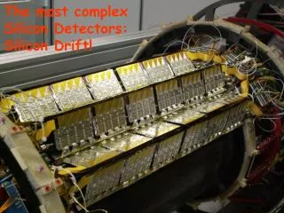
NA32 Experiment North Hall CERN 1984 Two CCDs, active area 0.5 Mpixels total, 1 and 2 cm beyond the target Ambleside School Chris Damerell
A pixel detector provides maximum information per layer, free of ghost hits 1 mm2 of sparsified data, both layers shown together 200 GeV ‘jets’, Clean pattern recognition by only two pixel planes Fred Wickens on shift 1984, ‘Do you think this looks like a charm decay?’ [After momentum analysis and particle ID, it proved to be our first D+ ] Ambleside School Chris Damerell
While we had our hands full trying to build a detector with <1 Mpixel, we also had our eyes on the even bigger physics goals associated with the next generation of e+e- colliders, LEP and SLD Ambleside School Chris Damerell
Vertex detectors were urgently needed (but not yet working) in the much more challenging collider experiments: • ‘Some presently marginal signals (such as the top quark in UA1) could be transformed into definitive experimental results with the aid of vertex detectors …’ • Ch D, Proc SLAC Summer Institute 1984, p 45 • Discouraged by the prospects at LEP (Villars workshop June 1981), but encouraged by discussions at the Fermilab workshop on silicon detectors (Ferbel and Kalbfleisch) in October 1981, we decided to join SLD … But what happened to the ‘drinking straw’? still 4 times better than LEP, at the time SLD Advisory Gp Mtg Feb 1989: “480 CCDs is ridiculous!” Ambleside School Chris Damerell
Ambleside School Chris Damerell SLC, another ‘good idea’ at SLAC, and a 307 Mpixel vertex detector
September 1991 Ambleside School Chris Damerell
SLD’s upgrade vertex detector VXD3: Su Dong: ‘That’s the vertex detector I joined SLD to build’ Installed 1995 307 Mpixels Layer thickness 0.4% X0 Rbp = 25 mm Ambleside School Chris Damerell
ILC Overall length ~ 35 km, about 10 times SLAC linac in size and energy reach Each of two detectors may weigh 1-10 ktons, and operate in push-pull mode Beam is delivered in 3000-bunch trains of duration 1 ms, every 200 ms Could be running before 2025, if early LHC results are encouraging, and some country or region bids to host, unless overtaken by CLIC … Ambleside School Chris Damerell
In contrast to the previous (Mark II) vertex detector, the SLD detector was extremely robust, even in sometimes high background conditions. It also easily established the ‘world record’ for performance (impact parameter precision as fn of momentum) and hence far more physics-per-event than at LEP (1/40 of LEP data, but world’s best measurements for charged and neutral B lifetimes, Rb, AFB (b) AFB (c), Bd and limit on Bs mixing … • This led to an explosion in R&D for all sorts of novel pixel sensors that might be used as vertex detectors at ILC. All are monolithic silicon-based • However, the technology choice is still wide open between ~ 8 options • Partly related to the broader debate between CCD and CMOS imaging devices (Fossum) • More on this later today, but let’s take a quick look at one option, which is helping to pioneer a new trend in silicon imaging devices … Ambleside School Chris Damerell
In-situ Storage Image Sensor (ISIS) • Beam-related RF pickup is a concern for all sensors converting charge into voltage during the bunch train; • The In-situ Storage Image Sensor (ISIS) eliminates this source of EMI: • Charge collected under a photogate • Charge is transferred to 20-pixel storage CCD in situ, 20 times during the 1 ms-long train • Conversion to voltage and leisurely readout in the 200 ms-long quiet period after the train, RF pickup is avoided • 1 MHz column-parallel readout is sufficient • Output for each bunch train thus comprises 20 frames of low-noise data, and this level of time-slicing will suffice for anticipated ILC backgrounds Ambleside School Chris Damerell
ISIS – plan view 5 μm Global Photogate and Transfer gate • Even more important: • Entirely avoids need for ‘pulsed power’ • Easier to drive because of the low clock frequency: 20 kHz during capture, 1 MHz during readout • ~100 times more radiation hard than conventional CCDs – far fewer charge transfers • ISIS combines CCDs with CMOS in one device: a member of the new family of ‘charge-coupled CMOS’ pixels [Sunday’s talk] • “Proof of principle” device (ISIS1) designed and manufactured by e2V Technologies, tested successfully at RAL last year • Prototype in 0.18 mm CMOS (ISIS2) designed at RAL and manufactured at Jazz Semiconductors, now under test at RAL and Oxford U ROW 1: CCD clocks ROW 2: CCD clocks On-chip switches On-chip logic ROW 3: CCD clocks ROW 1: RSEL Global RG, RD, OD RG RD OD RSEL Column transistor Ambleside School Chris Damerell
55Fe signal on test structure - Gary Zhang – 4 June Mn(Ka) Hits on O/P node ~6 (mm)2 Mn(Kb) ADC counts, ~12 e-/count • Such energy resolution never seen in CCD-based vertex detectors. Secret is mainly the responsivity of the output node: 24 mV/e- compared with about 3 mV/e- with CCDs • Shaping time matched to 7 MHz readout; rms noise 5.5 e- • Promises micron precision in centroid finding for MIPs with ~normal incidence Ambleside School Chris Damerell
“There is one thing stronger than all the armies in the world; and that is an idea whose time has come” Ambleside School Chris Damerell
Conclusions • From small beginnings 30 years ago, silicon-based pixel detectors have become the ‘preferred option’ for vertex detectors in particle physics, and are poised to expand into the volume occupied by general tracking detectors, in many cases displacing gaseous and silicon strip detectors • As well as ILC, there are exciting near-term applications at 4th generation SR sources (LCLS and XFEL); fast-frame X-ray cameras for molecular biology and other fields • The rapid evolution of charge coupled CMOS pixels provides an ‘enabling technology’ which will enhance the prospects for ILC vertexing and tracking (for the latter topic, see next talk) • An opinion in one of the LOI groups is that ‘the better is the enemy of the good’, but when there’s time to develop the better, why not go for it? Ambleside School Chris Damerell
Backup Ambleside School Chris Damerell
It turns out that both funnel and register have been fabricated by e2V for confocal microscopy: 100% efficient for single photoelectrons – noiseless, by using LLL (L3) linear register Diameter of outer active ring ~ 100 mm [David Burt, e2V technologies] Ambleside School Chris Damerell
ISIS2 test structure – short CCD SG OG OD PG Node RSEL ID IG (OS1) RG RD Polysilicon gates (undoped, no silicide) are ‘slow as molasses’ Short-channel and fringing field effects are large. Former have been simulated, latter not yet, but we can infer some things from our experimental results … Ambleside School Chris Damerell
For 2 months, we were effectively at ~2.5 V Results of 20 Feb 2009 Good performance when VOG = -0.2 V Ambleside School Chris Damerell
ISIS2 – Chip Layout Odd outputs (16 pads) Substrate ring (5 mm 5 mm) N+ guard ring A B C D Independent controls for each variant (12 pads) Row decoder 32 (H) 128 (V) pixels Row selection 8 8 8 8 1280 μm 32 (H) 128 (V) pixels 8 design variants in each 2.5x2.5 mm chip, 4 chip designs, 6 processing variants: overall 192 prototypes to test. How? 2560 μm Even outputs (16 pads) Ambleside School Chris Damerell
ISIS-3 and beyond • ISIS-3 could be a relatively inexpensive small-area prototype, incorporating all we learn from ISIS2, and using Jim Janesick’s Sandbox facilities • Once ISIS-3 works, one would want to move to ladder-scale devices, and their assembly into a telescope for evaluation in a high energy test beam circa 2012 • Limited to ~20 time slices with this 0.18 mm technology, but one could double or triple that figure by stacking the devices in a ‘vertically integrated’ or 3-D structure. One would use tier-1 for time slices 1-20, tier-2 for slices 21-40, etc • This would preserve the key ISIS selling points of complete freedom from pulsed power, and pickup-immunity during the train 20x20 mm imaging pixel Simple p-epi ‘channel stop’ ~1 mm wide [Assumes the process variation of ‘implant before patterning’ gates can be exploited to also permit gate connections in the storage register area] Ambleside School Chris Damerell
Results from Jim Janesick, December 2008, also working with Jazz Semiconductors 100 0 Ambleside School Chris Damerell
! Ambleside School Chris Damerell
ISIS-2 - pixel layout in main array BC reset SC reset 10 mm One of 32 readout columns photogates Successful charge transfers observed 21st July 2009 Ambleside School Chris Damerell
55Fe signal from photogate of main array Rhorry Gauld – 12 July • Signal survives transfer through 20 storage cells! • Broadened by large dark current contribution – as ‘expected’? • Watch this space …
Noise performance – 2 June 2009 – Gary Zhang – 5.5 e- ! Signal risetime 133 ns CDS with 800 ns between samples Measured noise (S.D.) = 5.5 e- totally stable for reduced sampling interval 30% increase in bandwidth produces expected sqrt(1.3) increase in noise Wider operating range of risetime and CDS interval (for slow-scan applications) will be explored ADC counts, ~3 e-/count Ambleside School Chris Damerell