Download
1 / 7
180 likes | 423 Views
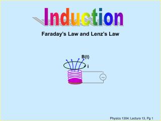
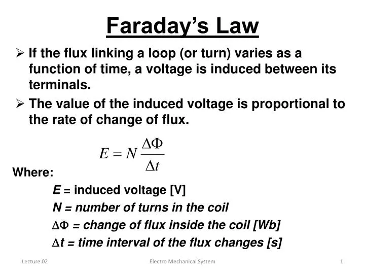
Faraday’s Law. If the flux linking a loop (or turn) varies as a function of time, a voltage is induced between its terminals. The value of the induced voltage is proportional to the rate of change of flux. Where: E = induced voltage [V] N = number of turns in the coil

E N D
Faraday’s Law • If the flux linking a loop (or turn) varies as a function of time, a voltage is induced between its terminals. • The value of the induced voltage is proportional to the rate of change of flux. Where: E = induced voltage [V] N = number of turns in the coil = change of flux inside the coil [Wb] t = time interval of the flux changes [s] Electro Mechanical System
Faraday’s Law • Example: • A coil of 2000 turns surrounds a flux of 5 mWb produced. by a permanent magnet.The magnet is suddenly withdrawn causing the flux inside the coil to drop uniformly to 2 mWb in 1/10s. What is the induced voltage? Electro Mechanical System
Voltage Induced in a Conductor • It is often easier to calculate the induced voltage on a segment of conductor instead of the voltage on a coil • E = B l v • Where: • E = induced voltage [V] • B = flux density [T] • l = active length of conductor in the magnetic field [m] • v = relative speed of the conductor [m/s] Electro Mechanical System
Voltage Induced in a Conductor • Example: • A stationary conductor of a large generator have an active length of 2m and are cut by a field of 0.6 teslas, moving at a speed of 100m/s. Calculate the voltage induced in each conductor. Electro Mechanical System
Lorentz Force on a Conductor • A current-carrying conductor sees a force when placed in a magnetic field • Fundamental principle for the operation of motors. • The magnitude of the force depends upon orientation of the conductor with respect to the direction of the field. • Force is greatest when the conductor is perpendicular to the field. • The Lorentz or electromagnetic force: • F = B l ISin • Where:F = force acting on the conductor [N] • B = flux density [T] • l = active length of conductor in the magnetic field[m] • I = Current in the conductor [A] • = Angle between the flow directions of current & flux Electro Mechanical System
Lorentz Force on a Conductor • Example: • A conductor 3 m long is carrying a current of 200 A and is placed in a magnetic field with a density of 0.5 T. Calculate the force on the conductor if it is perpendicular to the lines of flux. Electro Mechanical System
Direction of Force on Conductor • Current carrying conductor is surrounded by a magnetic field. • The flux lines of two magnetic fields never cross each other. • The flux lines of two magnet fields are vectorally added. • The generated mechanical force tends to push the lines of flux back to an even distribution. • Right hand rule • Point fingers in the direction of current flow (+ve to - ve). • Bend fingers into the direction of the magnetic field (N to S). • Thumb points in the direction of force . Electro Mechanical System