Download
1 / 19
190 likes | 206 Views
This study explores the reconstruction of coronal mass ejections (CMEs) using coordinated imaging and in-situ observations. It compares forward modeling of CME images and in-situ measurements to provide insights into the global structure, propagation direction, and orientation of CMEs. The study also discusses the challenges faced and future prospects in CME studies.

E N D
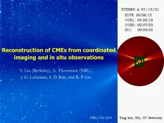
Reconstruction of CMEs from coordinated imaging and in situ observations Y. Liu (Berkeley), A. Thernisien (NRL), J. G. Luhmann, S. D. Bale, and R. P. Lin SWG, Feb 2009
Forward modeling of CME images • Geometric model with a flux rope morphology (density only); • Calculate Thomson scattering and compare with images observed by STEREO A, B and SOHO; • Can give the global structure of CMEs, propagation direction, true velocity, and flux rope orientation. Thernisien et al, ApJ, 2006
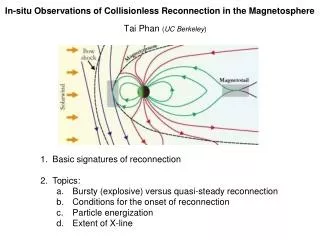
In situ measurements and reconstruction • Reconstruction with in situ data can give the flux rope orientation, cross section, and field chirality; • Goal: how comparison between in situ reconstruction and image modeling puts constraints on the global structure, propagation direction and orientation of CMEs. Liu et al, ApJ Lett., 2008
The 2007 Nov 14 – 19 CME / ICME Three views of the CME: Separation between A and B is about 40 deg. COR2 B LASCO/C2 COR2 A
The 2007 Nov 14 – 19 CME / ICME • Can see the CME all the way to HI2 (STEREO B only); • Flattened and concave outward.
The 2007 Nov 14 – 19 CME / ICME STEREO A STEREO B SOHO • Flux-rope forward modeling: • Agreement is good; • Propagation direction: 56 deg from the Sun-Earth line (west), and 19 deg below ecliptic; • Title angle: 21 deg relative to ecliptic.
The 2007 Nov 14 – 19 CME / ICME Observed and model images for STEREO B / HI1 at 3 times: Nov 16, 10:09 Nov 15, 16:09 Nov 15, 20:09
The 2007 Nov 14 – 19 CME / ICME • True velocity of the CME nose: ~450 km/s above 20 Rsun; • Bigger errors for HI1 due to CME flattening.
The 2007 Nov 14 – 19 CME / ICME In situ data: CME is observed at Earth and STEREO B, but missed at A? STEREO B ACE / WIND STEREO A
The 2007 Nov 14 – 19 CME / ICME • In situ reconstruction: • ACE: axis elevation angle -1.4 deg, azimuthal angle -106.7 deg (RTN); • STEREO B: axis elevation -33.8 deg, azimuthal 91.8 deg (RTN); • Both are left handed with the axis below ecliptic (propagating southward). STEREO B ACE
The 2007 Nov 14 – 19 CME / ICME • Comparison between image modeling and in situ reconstruction: • Propagation direction is below ecliptic, true for both imaging and in situ; • Flux rope tilt angle is roughly consistent (21 deg from imaging, 1 – 33 deg from in situ; • Contradiction: CME is toward A but missed at A? Distortion by the solar wind? Flux rope rotation?
The 2008 Dec 12 – 17 CME / ICME Three views of the CME: Separation between A and B is about 87 deg, optimal for stereoscopy.
The 2008 Dec 12 – 17 CME / ICME Can see the CME all the way to HI2 in both A and B.
The 2008 Dec 12 – 17 CME / ICME • Flux-rope forward modeling: • Wireframe rendering superposed on observed images; • Propagation direction: 1 deg from the Sun-Earth line (west), and 9 deg above ecliptic; • Title angle: 49 deg relative to ecliptic. STEREO B STEREO A
The 2008 Dec 12 – 17 CME / ICME Observed and model images in HI1 at 2 times: Dec 12, 23:29; Dec 13, 04:49. STEREO B STEREO A
The 2008 Dec 12 – 17 CME / ICME • True velocity of the CME nose: ~500 km/s above 20 Rsun; • Bigger errors for HI1 since the CME becomes fainter.
The 2008 Dec 12 – 17 CME / ICME • In situ data and reconstruction: • Axis elevation angle -6.4 deg, azimuthal angle -274.9 deg (GSE); • Left handed with the axis above ecliptic (propagating a little bit northward); • Missed at STEREO A and B?
The 2008 Dec 12 – 17 CME / ICME • Comparison between image modeling and in situ reconstruction: • Propagation direction is above ecliptic, true for both imaging and in situ; • Flux rope tilt angle at 1 AU is smaller than that deduced from images (6.4 deg from in situ but 49 deg from images); • Flux rope axis azimuthal angle is consistent; • Distortion by the solar wind and/or flux rope rotation cannot be ignored.
Future work CME studies with coordinated imaging, Faraday rotation and in situ observations: Faraday rotation gives field structure (Liu et al., ApJ, 2007) In situ data gives constraints Images give density structure