Download
1 / 16
170 likes | 480 Views
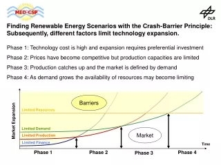
Challenges and limitations of thermosiphon cooling What we learned from CMS … Philippe Brédy CEA Saclay DSM/Dapnia/SACM/LCSE. The thermosiphon principle (example of two phase ) Self sustained natural boiling convection Heating applied (Heat to be removed) Boiling

E N D
Challenges and limitations of thermosiphon coolingWhat we learned from CMS…Philippe BrédyCEA SaclayDSM/Dapnia/SACM/LCSE
The thermosiphon principle (example of two phase ) • Self sustained natural boiling convection • Heating applied (Heat to be removed) • Boiling • Weight unbalance between legs of a loop • Induced flow limited by friction Q Single channel Loop
Rising heat exchangers with various geometry • A mass flow and a flow quality deduced from geometry and heat load • An upper tank –the well-named phase separator- is needed • to recover gas and to supply supply or condensation of gas (cryocooler) • for separation of the two phases DP flow (m,x,geometry) DP (x, hi) Hyp: homogenous model (x << 10%)
Advantages vs Inconveniences • A passive creation of flow • no pumps or regulation valves • Autonomy in case of external cryogenic failure (volume of liquid in the phase separator) • Minimization of the liquid volume • use of the phase separator as a back-up volume for liquid • A quasi-isothermal loop • mainly function of height • Need a minimum height • Pressure head to create flow • Circuit geometry must avoid any high point or strong singularities • separation of the phases • risk of vapor lock • No possible external action • and a possible frustration for the operator ! • Pre-cooling before starting the ThS effect
Examples of applications on large superconducting magnets with LHe/GHe loop at Tsat ATLAS CS (LHC) … CMS (LHC) ALEPH (LEP) SMS G0 (JLAB) CLOE (CORNELL) PANDA, R3B (GSI)…
CMS Phase separator cryostat • 220 tons at 4.5 K • 174 to 500 W at 4,5 K • 5 modules • 86 parallel exchangers Coil cryostat X 2 X 5
Phase separator cryostat (892 l GHe+LHe) Cryogenic chimney Thermosiphon loop (350 l) 5 LHe/GHe return pipes 48.3 x 1.6 LHe supply pipe 60.3 x 1.6 Outlet manifolds ( 45 x 2.5) Top Heat exchangers (i 14) CB-2 CB-1 CB+2 CB0 CB+1 Inlet manifolds ( 45 x 2.5) Bottom CMS thermosiphon First global calculation : x = 3,5 % ( 6,5% in SD) m = 200 g/s ( 400 g/s in SD)
Height between outflow and liquid level LHe tank Altitude 0 e (3.04) Upstream line (4.56) Venturiflowmeter Collecting manifold ( 0.04) 7 heat exchanger tubes (5.00 ) Hydrostatic head 9.22 (level at 50 %) Distributing manifold ( 0.04) CMS R&D Experimental test loop scaling CMS design
CMS R&D (scaling values) (on experimental test loop 1/10 CMS) CMS dynamic heat load CMS static heat load • A strong mass transfer in comparison with heat deposit • A large margin • Homogenous model correct still above 14% • h > 1600 W.m2.K • DPr/Dps 1 • DT height ~ 60 mK • x < 3% (CMS nominal) Experimental and homogenous model
CMS R&D • Self-sustained circulation with the heat deposited (on experimental test loop) 4.80 K 150 W total mass flow vsdifferent heat loads 125 W 4.72 K 100 W 4.64 K 75 W 4.56 K 50 W temperatures 4.48 K 25 W 0 W 4.40 K time
CMS on site • Self-sustained circulation with the heat deposited (on site, at the beginning of a slow dump with dynamic heat load) current mass flow
CMS on site • Stabilisation and increase of the mass flow by heating the return lines T Effect on the coil temperatures t - 0.01 K temperature decrease on coil Mass flow Effect on the mass flow - Increasing and stabilization of mass flow rate
CMS R&D • Smooth sensitivity near and above the critical point Pc
Limitations and Extensions • Feeding of several parallel circuits with different heat deposits is possible (in CMS design, in ratio of 5) (feeding and collecting pipes must be designed to be as isobaric) • Starting the natural circulation is achievable before the liquid presence (between 15 and 20 K for CMS design) • Heaters on the return pipes could be used to limit instabilities due to gas/liquid separation at low velocity (low heat load or over-sizing) • Flow quality could be chosen well higher than the traditional limit of 5 % • Circuit geometry : • A minimum height • Risk of high point or singularities where gas could be separated from the liquid • Minimization of pressure drop (singularities) • A quasi-adiabatic supply line • Good separation phase in the upper tank (what could be its minimum size?)
Conclusion Confirmed by these tests and operation measurements, thermosiphon loop stays a convenient way to insure the indirect cooling of large equipment and must be taken into account during a design study without preconceived fears.
References • 1. L. Benkheira, B. Baudouy, and M. Souhar, Heat transfer characteristics of two-phase He I (4.2 K) thermosiphon flow, International Journal of Heat and Mass Transfer, (2007) 50 3534-3544 • 2. L. Benkheira, B. Baudouy, and M. Souhar, Flow boiling regimes and CHF prediction for He I thermosiphon loop, Proceedings of the 21th International Cryogenic Engineering Conference, to be published, Ed. G. Gistau, (2006) • 3. P. Brédy, F.-P. Juster, B. Baudouy, L. Benkheira, and M. Cazanou, Experimental and Theoretical study of a two phase helioum high circulation loop, Advances in Cryogenics Engineering51, AIP, Ed. J. G. Weisend, (2005) 496-503 • 4. L. Benkheira, M. Souhar, and B. Baudouy, Heat and mass transfer in nucleate boiling regime of He I in a natural circulation loop, Advances in Cryogenics Engineering51, AIP, Ed. J. G. Weisend, (2005) 871-878 • 5. B. Baudouy, Heat transfer near critical condition in two-phase He I thermosiphon flow at low vapor quality, Advances in Cryogenic Engineering49, AIP, Ed. S. Breon, (2003) 1107-1114 • 6. B. Baudouy, Pressure drop in two-phase He I natural circulation loop at low vapor quality, International Cryogenic Engineering Conference proceedings19, Ed. P. S. G. Gistau Baguer, (2002) 817-820 • 7. B. Baudouy, Heat and mass transfer in two-phase He I thermosiphon flow, Advances in Cryogenic Engineering47 B, AIP, Ed. S. Breon, (2001) 1514-1521