Download
1 / 31
310 likes | 446 Views
Status of JINR participation in the ILC. G. SHIRKOV GDE Meeting, Dubna, June, 4, 2008. Armenia Azerbaijan Belarus Bulgaria Cuba Czech Republic Georgia Kazakhstan Democratic People’s Republic of Korea. Moldova Mongolia Poland Romania Russia Slovak Republic Ukraine Uzbekistan

E N D
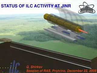
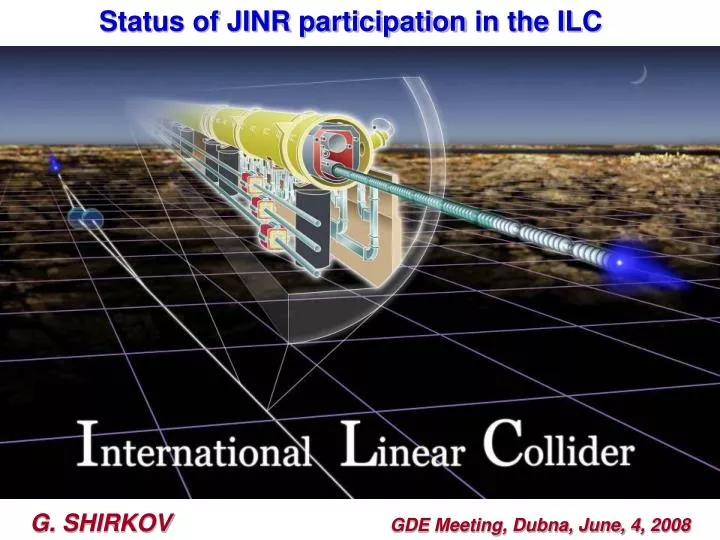
Status of JINR participationin the ILC G. SHIRKOV GDE Meeting, Dubna, June, 4, 2008
Armenia Azerbaijan Belarus Bulgaria Cuba Czech Republic Georgia Kazakhstan Democratic People’s Republic of Korea Moldova Mongolia Poland Romania Russia Slovak Republic Ukraine Uzbekistan Vietnam Joint Institute for Nuclear Research: International Scientific Centre Associated member-states: Germany, Hungary, Italy, South Africa, Serbia. We expect China and France to joint JINR as associated members in 2008
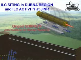
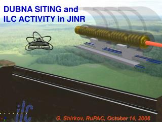
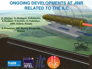
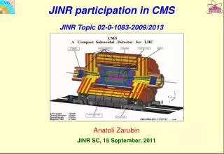
ILC Activity in Dubna: • proposals of ILC sitting in the Dubna region; • participation of JINR in the ILC international technical activity and related investigations with electron beams
Layout of ILC in the Moscow Region Tver region Moscow region
Main Linac Double Tunnel Conventional Facilities • Three RF/cable penetrations every rf unit • Safety crossovers every 500 m • 34 kV power distribution • 72.5 km tunnels ~ 100-150 meters underground (for US, Asia, and CERN cites) • 13 major shafts > 9 meter diameter • 443 K cu. m. underground excavation: caverns, alcoves, halls • 92 surface “buildings”, 52.7 K sq. meters = 567 K sq-ft total
Documentation and Cost Estimation July 2006 (for Vancouver GDE): JINR prepared and filled the necessary documents for possible ILC hosting to BCD (CFS chapter) – the Site Assessment Matrix. • Official document from Russian State Project Institute (GSPI, Moscow) with estimations on: • Conventional facilities cost • Siting (tunnel, land acquisition) cost and time schedule • Energetic and power cost • Operational cost • Labor cost November 2006 (for Valencia GDE): JINR prepared and filled the necessary documents as a sample site for possible ILC hosting to RDR (Work Breakdown Structure - WBS). This document was also prepared with GSPI and submitted by Design Cost Board of GDE. Russian State Project Institute (GSPI, Moscow) – the most powerful and professional institute in Russia with 60 years history: design and construction of almost all Soviet and Russian Nuclear power stations, Nuclear centers (Sarov, etc), Scientific Nuclear accelerator centers (JINR Dubna, IHEP Protvino, ITEP Moscow, INR Troitsk, etc)
The ILC linear accelerator is proposed to be placed in the drift clay at the depth of 20 m (at the mark of 100.00 m) with the idea that below the tunnel there should be impermeable soil preventing from the underlying groundwater inrush. It is possible to construct tunnels of the accelerating complex using tunnel shields with a simultaneous wall timbering by tubing or falsework concreting. Standard tunnel shields in the drift clay provide for daily speed of the drilling progress specified by the Project of the accelerator (it is needed approximately 2.5 years for the 50 km tunnel).
A new suggested variant of the accelerator tunnel layout is under discussion and estimations now. It assumes the following: • main (beam) tunnel is located at approximately -20 m (at abs. level -100 m) in order to have impermeable layer above and below to be prevented from subsoil waters; • service (communication) tunnel is located directly above the main and around the earth surface (<-3-4 m), practically repeating the relief; • technological connection between two tunnels is provided with vertical shafts of different diameters, which are drilled with usual method; • connection between surface buildings and underground infrastructure is provided with vertical and horizontal shafts (elevators, stairs, etc). • Such a variant is more efficient economical by several reasons: • Service (communication) tunnel can have any size (section) for loading or filling the beam tunnel with any equipment, it is made by open-cut method; • Vertical connections are made by well-boring (relatively cheap method in comparison with case of horizontal ones), at the same time their number and sizes can be optimized. In addition – they do not require damp course; • Export of the drain waters is provided directly in accordance with relief, without any pumping stations; • Exploitation of the communication tunnels is sufficiently easier; • Cable and other technological connections between service tunnel with surface building is sufficiently reduced.
GSPI proposal: Shallow site with single tunnel buildings Communication tunnel Vertical shaft 0 -1,0 vertical communication shaft -20,0 accelerator tunnel
Advantages of the ILC construction in Dubna: • JINR as a basic scientific and organizational structure with international intergovernmental organization. • Prevalent legal practice makes it possible to get the land of the ILC location to permanent free use just as it has been done for JINR, according to the agreement between JINR and the RF government. • The proposed territory is extremely thinly populated and practically free of industrial structures, rivers and roads. • The area is absolutely steady seismically and has stable geological characteristics. • A flat relief and geological conditions allow to place ILC on a small depth (about 20 m) in the dry drift clayand to perform construction of tunnels, experimental halls and other underground objects with the least expenses, including cut-and-cover.
6. Sources of the electric power of sufficient capacity: transmission line of 500 kV, the Konakovo electric power station and the Udomlia atomic power plant. 7. The developed system of transport and communication services, good highways and railways, water-way (the Volga river basin); 8. Presence of a modern network and information infrastructure, including one of the largest center in Europe the “Dubna” Satellite Communication Center. 9. A special the economic zone in Dubna provides preferential terms for development and manufacture of high technology technical production. 10. A powerful scientific and technical potential of Dubna makes it possible to involve additionally specialists from world scientific centers into the international collective of highly-qualified scientific manpower. 11.The only one shallow tunnel with accelerator structures and communication gallery on the surface
Plans of site investigations (provided with Moscow region government) • Basic data acquisition for construction R&D works of ILC project. • To provide routing researches with the description of characteristics of the offered line of the accelerator location and the infrastructure connected with it; • To specify character of surface structures, real population, topographical features (including depth of the crossed rivers and other reservoirs), an actual accessory and economic use of the wood and ground resources getting in a zone of alienation of the accelerator; • To check a real state of a road network in area of prospective construction, an opportunity of its use at a stage of a pre-construction works and during a construction and operation of an accelerating complex; • To provide drilling of several control prospecting chinks for acknowledgement of prospective soil structure on the chosen line of the accelerator location.
Participation of JINR in the ILC International Technical Activity International Linear Collider: accelerator physics and engineering • Theme leaders: A.N. Sissakian G.D. Shirkov • Period: 2007- 2009 • Preparation of works of JINR; • Participation in estimations • and design of ILC elements
1. Construction of ILC photoinjector prototype. 2. The LINAC-800 based test-bench with electron beam 3. Development of power supply devices for RF system 4. Metrological laser complex 5. Development and design of cryogenic modules and test systems. 6. Preparation of technical base of cryogenic supply to test cryomodules of the 4th gen. 7. Calculation of electrical and magnetic fields 8. Engineering survey and design works 9. Development of the electron cooling method. LEPTA project. 10. Project CLIC 11. Project FLASH 12. Development of diagnostic systems; development of built-in devices. 13. Development of magnetic systems of the ILC damping rings 14. Development of diagnostics for large cryogenic systems. Personnel ~ 100 persons In total year 2007 ≈ 900 k$ (personnel 580 k$ + travels 90 k$ + R&D 230 k$)
CLIC: Continuation of works with CERN: new prototype of the resonator was manufactured, proposed ways for increasing of the pulsed heating, results of the works on 2nd stage of the Contract approved by CERN, detailed program of experimentsin the frame of the 3rd stage had been agreed, next stage of the modernization of power supplies for LIU-300 focusing lenses Is in progress. LINAC-800: Commissioning of the accelerating section (20-40 MeV) - May 08 Construction works at b.118, engineer infrustructure, modulator test bench, klystron test bench) Participation of the LINC-800 team in NICA project – coordination of works on new heavy ion LINAC – Contract with IHEP, Protvino)
Test bench “Electron linac LINAC-800 1. Assembled and tested on vacuum the injector node: electron gun + buncher. Vacuum is 2•10-8Torr (corresponds to the project requirements). 2.Created and tested modernized the control subsystem for injector electron gun. 3. Control room is created: mounted power supply block (400 kV). Constructed and fixed power stabilizers, mounted regulated high voltage power supply (1 kV) for modulator rectifier. 4. Mounted and commissioned RF generator at equivalent load. Buncher at low level of RF power is tested. 5. Assembled, mounted and tested equipment for testing of modulators for klystrons. Forming line of A00-01 modulator station is under testing and construction. 6. Assembly and test of magnetic system elements was performed at test bench of FEL IR. Undulator magnetic field tuned with accuracy better then 0,5 % 7. RF test bench for accelerator mounted on the base of operational klystron “Thompson TH 2129”. 8. Researches of photoemission characteristics of the injector cathode at the special test bench for investigations of the DC photoinjectors were started
Injector pass: electron gun + chopper + pre-buncher. RF test bench on the base of operational klystron “Thompson TH 2129”. Cathode test-bench
JINR Participation in the ILC Cryomodule design. This international effort includes contributions from many institutions, including JINR together with FSUE “RFNC-VNIIEF” (Sarov, Russia). The key participants at the JINR are J.Budagov, B.Sabirov and A.Sukhanova. In the recent months JINR and Sarov have started a collaboration with INFN-Pisa on a bi-metallic Ti-SS transition tube to connect the Titanium helium vessel with a 76-mm diameter two-phase helium line in an ILC cryomodule (CM). Such a transition would allow for a very substantial cost savings in the ILC cryomodule production. Successful preliminary tests with prototype transition tubes of a smaller diameter, supplied by JINR and Sarov, were conducted by JINR in collaboration with INFN-Pisa.
Test results create a great impression at ILC Meeting in Florence. In the future the collaborative R&D of bi-metallic tubes for the ILC cryomodule and testing them should be done in conformance with the Technical Specifications. For more statistic a total of twenty tubes will then be delivered to Fermilab for further integration into a cryomodule. JINR with Sarov will carry out the work for production 10-20 units of the bi-metallic tubes will be sent consequently to the INFN/Pisa and FNAL following the schedule parties will agree timely. The tubes will be used at FNAL and in Pisa for ILC purposes.
Photo injector prototype activity Yu.Korotaev, V.Lokhmatov, I.Meshkov, G.Shirkov, G.Trubnikov Main results in 2007: - JINR scientists worked in operation runs at PITZ and FLASH. Several scientific missions of JINR staff to DESY Hamburg and Zoethen were done. - JINR performed design and started construction of the test bench for CsTe photocathode preparation. This test bench is planed to be used for preparation of GaAs photocathode in future. - 8 publications in 2007:
Laser metrology JINR developed test bench at CERN for precise laser metrology. Results ofAug’06 0,5 micron precision of laser beam position measurement on the base of 40m is achieved. At JINR it is planned to set this complex at b.118 (base is 2x250m). DR magnetic system simulations and magnet prototype construction Dr. E.Syresin, Dr. N.Morozov (with group) in collaboration with SLAC (A.Seryi) works on design and possibility to construct at JINR workshop series of magnetic system elements of DR (few dipole magnets). It is also planned to provide test of those elements. This activity is performed in frames of MoU JINR-KEK on ATF collaboration. Similar MoU between JINR and SLAC is under assignment Civil engineering Very fruitful collaboration with GSPI. All official documentations (Site Assessment Matrix, Work Breakdown structure, geological and geodetically characteristics) was made by GSPI in the frame of Contracts with JINR. Work is actively going on.
SHORT XFEL AND ILC BUNCH MEASHUREMENTS Parameters of FIR at FLASH - DESY constructed in JINR Coherent radiation of FLASH infrared undulator constructed at JINR
Magnetic measurements of infrared undulator at DLNP test bench January 2007, JINR
JINR infrared undulator applied for short bunch measurements in FLASH-DESY tunnel June 2007, DESY
SCHEME OF ILC MAGNET SPECTROMETER Scheme of magnetic spectrometer applied for ILC beam energy measurement.
JINR MEASUREMENTS OF SLAC LINAC ENERGY BY SPECTROMETER MAGNETIC MEASUREMENTS AND SIMULATIONS OF A 4-MAGNET DIPOLE CHICANE FOR T-474 AT SLAC, A BPM-BASED ENERGY SPECTROMETER PROTOTYPE FOR INTERNATIONAL LINEAR COLLIDER Viktor Duginov, Sergey Kostromin, Nikolay Morozov at al, PAC 2007 Two energy scans (calibration run at -150 A) Energy measurements technique was tested in joint research at T-474 at SLAC. Relative error of the energy definition is 2.5∙10-4 for this moment.
GEANT IV SINCHROTRON RADIATION SIMULATIONS OF ILC ENERGY RESOLUTION DETECTOR E=250 GeV+50 MeV- red histogram E=250 GeV-blue histogram SR fan left edge displacement xleft7-8 μm SR fan right displacement xright5-6 μm Coordinate/Energy resolution 12 μm/50 MeV Energy resolution is of dE/E=510-5 at coordinate resolution of 3 μm
High pressure system for ILC Synchroron Radiation Gas Amplification Detector A prototype of a gas amplification strip detector with 48 channels and resolution of 3 m was constructed. The construction of high pressure (150 atm) chamber for a gas amplification strip detector was performed.