Download
1 / 19
200 likes | 386 Views
Overview of GOCE Gradiometer Cal/Val Activities. J. Bouman , P. Brieden, G. Catastini , S. Cesare, R. Floberghagen, B. Frommknecht , R. Haagmans, M. Kern, D. Lamarre, J. Müller , G. Plank, S. Rispens, C. Stummer , C.C. Tscherning, M. Veicherts, P. Visser. GOCE Cal/Val LP Symposium 2010.

E N D
Overview of GOCE Gradiometer Cal/Val Activities J. Bouman, P. Brieden, G. Catastini,S. Cesare, R. Floberghagen, B. Frommknecht,R. Haagmans, M. Kern, D. Lamarre, J. Müller,G. Plank, S. Rispens, C. Stummer,C.C. Tscherning, M. Veicherts, P. Visser
GOCE Cal/Val LP Symposium 2010 • The in-flight calibration of the GOCE gradiometer (Cesare et al) • Alternative in-flight calibration of the gradiometer using ESA's L-Method (Lamarre and Kern) • Quality assessment of GOCE gradients (Müller and Brieden) • A methodology to use terrestrial gravity data sets for regional validation of GOCE products in central Europe (Schäfer et al) • First results using ESA's internal calibration method GRADNET(Kern et al) • External calibration of GOCE differential accelerations (Rispens) • Validation of GOCE with terrestrial gravity data in Norway(Gerlach and Pettersen) • External calibration of the GOCE gravity gradients at the High-Level Processing Facility (Bouman et al)
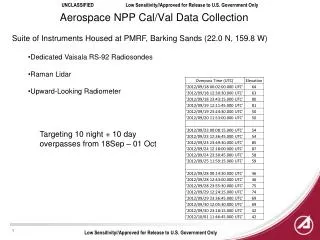
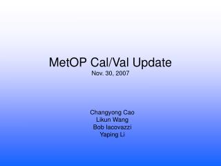
Gradiometer • 6 accelerometers measure in 3 orthogonal directions • Each accelerometer has two ultra-sensitive axes and one less-sensitive axis • OAG: One-Axis Gradiometer • GRF: Gradiometer Reference Frame
Single accelerometer and pairs • Ideal accelerometer measurements: • Gravity gradients • Rotational terms • Drag, solar radiation pressure, thruster action, … • Vibrations, self-gravity, … • Common and differential accelerations • Common = sum averaged drag etc • Differential = differences averaged gravity gradients and rotational terms • Pair of two accelerometers is OAG (One-Axis Gradiometer)
Real gradiometer measurements Measurements with a real gradiometer have errors due to: • different scale factors • axesare notperfectly aligned • sensitive axesare notmutually perpendicular • internal dynamics • accelerometers do not occupy their nominal positions • origins of the 3 OAGRFs do not coincide and their axes are not aligned • gradiometer configuration is time-varying
Real gradiometer measurements Acceleration measured by the accelerometerAi: ai= true acceleration a’i= measured acceleration [K]i = scale factor matrix [dR]i = rotation matrix (misalignment) [dS]i = accelerometer inter-axis coupling matrix [K2]i= quadratic factor matrix bi= bias ni= noise
On-ground verification In-flight accelerometer calibration Quadratic factors Calibration parameters (matrix) Accelerometer or satellite shaking External calibration and validation Accelerations or gravity gradients External gravity data and models GOCE Calibration Steps
Verification of design/manufacturing tolerances and of stability (e.g. K2) One-Axis Gradiometer (OAG) baselines were measured on ground and these values are used in flight On-ground verification
Twooperations: Quadratic factor (K2) adjustment Scale factor, coupling & misalignment determination Baseline method ESA L-method GRADNET In-flight calibration
Feed-back loop non-linear a = K0 + K1 V + K2 V2 + … Physically reduce K2 to zero (acceptable level) by test mass position adjustment Test mass shaking In-flight calibration: quadratic factors
For each OAG, common and differential: Couplings Misalignments Scale factors 54 calibration parameters (3*18) Relation between measured and corrected common & differential accelerations for one OAG (ij = 14, 25, 36): In-flight calibration: Inverse calibration matrices Three 6x6 calibration matrices Mij(scale factors, misalignments & couplings).Inverse calibration matrices MIij must be known to recover actual accelerations from the measured ones.
In-flight calibration: baseline method • Calibration matrices for each OAG determined separately (iterative process) • Satellite shaking enables relative calibration (all ICM elements except common scale factors) • Star sensor data used to determine 9 absolute (common) scale factors • Empirical relation between scale factors needed
In-flight calibration: ESA-L method • Equations in GRF instead of OAG (72 parameters) • 54 parameters are estimated • Co-estimate STR – gradiometer misalignment • Relative scale factors, relative positions and relative misalignments • One absolute scale factor, misalignment with respect to star tracker • ESA-L & baseline ICMs agree except for large • differences in common scale factors
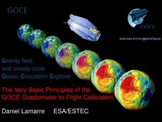
z(GRF) x(GRF) y(GRF) In-flight calibration: GRADNET • Accelerometers form a gradiometer network • Use redundancy within the network • ESA-L & GRADNET agree well • Gradiometer scale factors stable to better than 10-3 (a3x + a6x) / 2 = (a1x + a4x) / 2
External calibration of accelerations External calibration and validation of gravity gradients (GOCE Cal/Val Team) Global gravity field models Using GOCE GPS data Using terrestrial gravity data Validation in crossovers External calibration
Use GG from model tocalibrate GOCE GG GG scalefactordeterminedupto 10-3level External calibration:Global gravity field models GOCE Model
External calibrationGOCE GPS and terrestrial gravity data • GOCE GPS data • Estimation of global 80 x 80 gravity field combining GOCE GPS data and GGs • GG scale factors co-estimated • Terrestrial gravity data For each track in area GG SF estimated
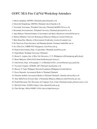
External calibrationValidation in crossovers (XO) Basic idea Identical measurement position • → identical gravity gradient: Vij,1 = Vij,2 Tasks • Interpolation of XO position and GG measurement along time series • Reduction of altitude and attitude effects in measurements XO-differences fit very well with GG noiselevel VXX, VYY: 98% < 15 mE VZZ: 98% < 25 mE
Summary • GOCE calibration is done in 3 steps: • On-ground verification • In-flight calibration • External calibration and validation • Absolute calibration requires reliable standard: not trivial • Result: • Gravity gradient data of good quality • Improved gravity field information • GOCE Calibration Splinter Meeting:Thursday 10 AM, Room Bøygen, Grieghallen