Download
1 / 21
210 likes | 714 Views
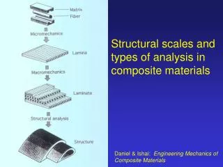
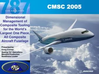
Dimensional Management of Composite Tooling for the World’s Largest One Piece, All Composite Aircraft Fuselage. Presented by: Craig Cramer Boeing 787 Operations Mandrel Production Readiness Leader. Composite Solutions Applied Throughout the 787. Other 5%. Fiberglass 10%. Carbon laminate.

E N D
Dimensional Management of Composite Tooling for the World’s Largest One Piece, All Composite Aircraft Fuselage Presented by: Craig Cramer Boeing 787 Operations Mandrel Production Readiness Leader
Composite Solutions Applied Throughout the 787 Other 5% Fiberglass 10% Carbon laminate Composites50% Titanium15% Carbon sandwich Fiberglass Aluminum Aluminum20% Aluminum/steel/titanium pylons
The Project • Build a complete Test and Certification Barrel of the Boeing 787 Dreamliner fuselage (The 787 Fuselage team). • Construct this all composite fuselage as a One Piece Skin-Stinger Bond Assembly. • The Barrel, when completely assembled with doors, windows, floors, etc., will be fatigue tested for FAA Certification. • Maintain commonality between Boeing, the world wide Partners and the Suppliers (The Production Readiness Team [PRT]).
Metrology Application • Metrology challenge: inspect the many surfaces of the Tools to optimize the as-built condition of each Sub-Assembly when the entire Tool is assembled • Model Preparation: Develop models, drive files and tolerances • Measurement Tasks: (using laser radar scanner and laser trackers) • Inspect Tools for Quality Assurance • Use As-Built data to optimally assemble the tool • Measure IML and OML after fuselage is cured • Provide collection data to optimize the manufacturing process • Data used in certification and validation of the manufacturing processes for the FAA
STP - Metrology • Situation: New manufacturing processes with shortened flow times require new methods for quickly analyzing data and generating feedback. • Target: The proposed test program must have fast feedback loops of the survey data. • Proposal: Use scripted measurement plans with Spatial Analyzer’s common interfaces to metrology systems, thus providing a closed loop control system with critical component features to automated product assembly. A Big Button interface for running the scripts simplifies shop floor implementation while enabling close process flow control. Embedded process checks and tolerances enable the script to handle real-world production assembly processes.
Situation (Old Method) NOM TOOL SURFACES MACHINE THE TOOL NOM NC PROGRAM Catia ENGINEERING SURFACES Catia STEP FILE TRANSLATOR FORMULATE THE INSPECTION PLAN CREATE NOMINAL INSPECTION FILE CHECK TOOL CREATE DRIVE FILE Spatial Analyzer Excel Catia PowerPoint Catia These processes may take several weeks because they are mostly manual input RESULTS REPORTED MEASURED DATA ANALYZED Excel
The Target • Seamless integration of measurement requirements in the Design/Quality Engineering and Production processes for 787 Fuselage Test Barrels. • Accurate and concise analysis of the data collected, verified directly to the digital model. • Rapid turn-around of collected data to support decision making. • Understandable reporting of the data to all participating parties, delivered in a timely/consistent manner. • Make the measurement results available enterprise-wide on the internet. • Future application for partner use on production airplane (digital portable solution). • All partners/suppliers use the same digital thread: common tie-in and verification method yield product consistency across the supplier/partner chain.
The Proposal • Form a team of metrology experts to script Measurement Plans. • Script measurement plans and assist in the surveys as needed (the team). • Use the same software throughout the process to avoid misinterpretation of data. • Use real time analysis capabilities, on screen, so the operator will know immediately if the data is valid. • Inspection buy-off can be done ‘on-the-spot’ as the survey is being taken, or hand stamped on the paper copy of the report, directly to the design model. • Generate reports ‘on-the-spot’ and/or send results to a server for instant observation upon survey completion (avoid delay). • Share reports enterprise-wide via the internet. • Use existing tools if possible (SA is currently accredited software in the Boeing Company).
The Plan(New Method) • Write integrated Scripted Measurement Plans and Analysis Tasks to avoid misinterpretation of data. • Use the same software to write Measurement Plans, perform the survey and provide analysis. • Reduce, or eliminate, the time consumed by manual analysis. • Rapid turn-around of analysis after data collection is complete. • Work directly with the CAD model. • Instrument observations, reference tie-in, and measurement uncertainties are captured, documented and communicated consistently, establishing a level of confidence in production deliveries.
New Method Flow NOM TOOL SURFACES MACHINE THE TOOL NOM NC PROGRAM Catia ENGINEERING SURFACES INSTANT FEED BACK Catia DRAFT THE PLAN DRIVE FILE & INSPECTION CREATION FORMULATE THE INSPECTION PLAN CHECK TOOL GENERATE REPORTS Spatial Analyzer Spatial Analyzer Spatial Analyzer Spatial Analyzer PowerPoint
Metrology Automation Concepts • Communication between components, including across process and network boundaries • Shared measurement process components (e.g., Locate Instrument, AutoMeasure, MeasureMode) • Quick error and status reporting • Conditional Branching, Looping, and Interactive Queries • Dynamic loading of components • Constructs for instrument control, compound documents, automation, data transfer, storage and naming
Templates and Measurement Plans • SA Template Files • CAD Model and Settings • Instruments Location and Settings • MP Script of Measurement Process • Load Template • Start Instrument Interface • Data Collection Drive Scanner & Rotate the Tool • Auto-Alignment to CAD • Feature Detection Extraction • Feature Analysis • Generate Report • Save and Archive Inspection
Template Creation • Model information transfer • Getting the drawing intent into the graphics software • Elements; Surfaces, Holes, Lines • Features; Datum's, Tolerances • Creation of tags • Modify design standards • Standard labeling methods • Defined Model layers
Measurement Plan Automation • Automated Drive File Creation – Feature Based
Templates CAD Model Instruments Measurement plan Initialize (load template) Enhancements Data Collection Registration/Fit to Features Feature Extraction Query/Analysis Process Checks Reporting Data Export Step (AP203,214) Documents: Word,Excel,AVI,HTML User feed back Pass Fail Graphics Tabular Save & Archive Operator interface Inputs (User info) Run Output MP Process Components
Data Exchange Model Tolerances Feature relationships Instrument Interface Drive Instrument Field checks Initial Instrument Alignment Process time Multiple instruments Translation/Rotation stages Integrating different Metrology Devices % of applications need two diff metrologies Master slave control Process triggers Examples: Robot & Scanner Scanner with Tracker Manage Process Elements
Acknowledgments Craig Neidig Boeing Commercial Airplanes 787 Tool Engineering File Creation David B. Holm Karl W. Kunst Boeing Management Scott Sandwith New River Kinematics Technical support M.J. Fjellestad Boeing Commercial Airplanes 777 Program Editing