Download
1 / 9
140 likes | 368 Views
Automobile Charging System. By Daniel Joo. Functional Diagram. Signal Conditioning. Voltage Regulation. Alternator. Alternator. C. A. B. AC Current. Rotor - Stator creates AC current Since there are three Stator, three separate ac signal are created. Signal Conditioning (Alt. to Bat.).

E N D
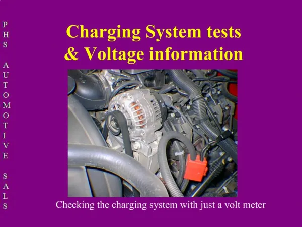
Automobile Charging System By Daniel Joo
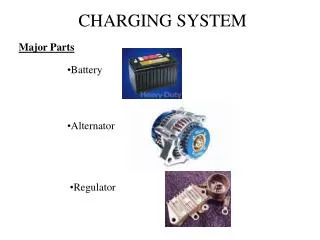
Functional Diagram Signal Conditioning Voltage Regulation Alternator
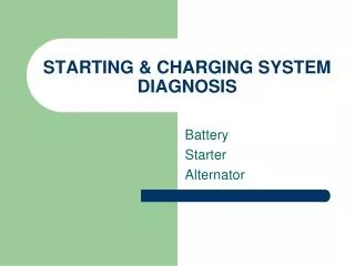
Alternator C A B
AC Current • Rotor - Stator creates AC current • Since there are three Stator, three separate ac signal are created.
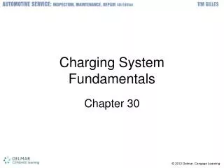
Signal Conditioning (Alt. to Bat.) • Typical Alternator Cicuitry. • AC from each of the alternators stators are filtered to only receive Positive current.
Alternator Rectifier • Signal from the alternator is rectified to form a positive pulsating signal.
Voltage Regulation • Voltage variations are due to: • Mainly Engine RPM • Temperature • Voltage is regulated through the current driving the STATOR.
Voltage at Alternator Rotor Voltage Control Input Regulator Field Current Input
Close Enough To 12V DC • Current in not pure DC, it is a series of DC pulses at 12 Vdc. • But most equipment have internal filters to clean-up the incoming power.