Download
1 / 13
130 likes | 277 Views
Inductively Coupled Charging System Requirements. Operating Depth: 5000m (16,400 ft) AO J-Box Supply Power < 100W Float Supply Power arbitrary Charge Time < 6 hrs (minimize) Charge Interval ~ 4 days Data Transmission Bi-directional >100kbps Vehicle Comm RS422 protocol

E N D
Inductively Coupled Charging System Requirements • Operating Depth: 5000m (16,400 ft) • AO J-Box Supply Power < 100W • Float Supply Power arbitrary • Charge Time < 6 hrs (minimize) • Charge Interval ~ 4 days • Data Transmission Bi-directional >100kbps • Vehicle Comm RS422 protocol • Battery Voltage 12 VDC 10.8VDC nominal • Battery Chemistry TBD (Lithium-Ion?) • Peak Charging Current < 20 amps • Supply Voltage 48 VDC • Charger Efficiency > 90% • Charge Algorithm Programmable (constant current then constant voltage) • On Board Size TBD (minimize) • On Board Weight TBD (minimize) • Operating time >2 years • Other Removable from cable Constant power draw from AO JBox (trickle charged float battery pack ?) Resistant to marine biofouling • Off Board Size TBD (minimize) • Off Board Weight TBD (minimize) • High Reliability use hi-rel components where appropriate consider redundant components/circuits minimize stress on components – thermal, electrical, etc.
PRIMARY SIDE POWER SYSTEM MICROCONTROLLER External Communication Local Battery Management Input Power From Current Source SHUNT REGULATOR PRIMARY SIDE BATTERY CHAEGER DC-HFAC CONVERTER Series-Resonant 100kHz RF/IR TRANSCEIVER DATA Link High Frequency AC Power PLATFORM CRAWLER Short Range RF/IR Link Inductive Power Coupler High Frequency AC Power Connection to Crawler Battery Voltage and Current Monitor Battery Charge Controller HFAC-DC ACTIVE RECTIFIER REGULAOR RF/IR TRANSCEIVER DATA Link CRAWLER SIDE POWER SYSTEM MICROCONTROLLER On-Board Communication
System Components Primary Side Microcontroller PC/104 based hardware to minimize Development Local Battery Management through Shunt Regulator On/Off Control of SRC Communication path Series Resonant Converter High Frequency AC Current Source Drive Inductive Coupler Constant Frequency (Open Loop) Operation Shunt Regulator Active Resistance to Provide constant power RF/IR Transceiver Short Range Link Explore Off the Shelf Options RF in 100s of MHz or IR in 800nm Same Device on Both Sides System Components Secondary Side Microcontroller Battery Management on Crawler Side Charge Algorithm Implementation Voltage and Current Sense State of Charge Tracking Communication to other systems on Crawler Data Link Communication path Low Power Consumption uP Active Rectifier Pass or Shunt HFAC Current High Electrical Efficiency Convert HFAC to DC Power Interface to Battery HF Filtering RF Transceiver Same Device on Primary Side Inductively Coupled Charging System Electronics
System Components Primary Side Core “C” core design Angled interface to secondary core reduces gap Flexure Provides necessary degrees of freedom for core alignment Enidine Wire Rope isolators (possible off the shelf device) Guide Structural support of Primary core Attachment to floater Houses communications interface Primary Winding Litz wire (Size, Turns: TBD) Charger Enclosure Houses Charger Electronics on Floater HFAC Cable Litz wire Interface from Charger to Coupler System Components Secondary Side Core 3/4 “C” core design Angled interface to secondary core reduces gap Guide Provides initial alignment of cores Reduces drag by secondary core Houses communications interface Structure to Crawler Provide attachment of secondary to crawler Secondary Winding Litz wire (Size, Turns: TBD) HFAC Cable Litz wire Interface from coupler to Crawler Electronics Inductively Coupled Charging System Mechanical
Guide (attached to Floater) Flexure (3-6) Charger Cable Primary Core Secondary Guide Secondary Core Inductively Coupled Charging System Mechanical
Guide (attached to Mooring) Flexure (3-6) Crawler Cable Secondary Guide Secondary Core Primary Core Inductively Coupled Charging System Mechanical
Inductively Coupled Charging System Mechanical Guide (attached to Floater) Location of Communication Link: Primary Secondary Secondary Core Guide Primary Core
Inductively Coupled Charging System Mechanical Secondary Core Guide Guide (attached to Floater) Secondary Core Angled core interface Crawler cable Primary Core
Standard crawler has primary LiSO2Cl2 (Lithium Sulfuryl Chloride) batteries with capacity for 106 meters of travel • Modified crawler will have rechargeable batteries selected and sized to maximize duty cycle, reliability and life • Charging current will affect battery life, C/2 recommended • Double click on table at left – shaded cells are for changing input variables
Li-Ion Charging • Programmable charger: • Stop charge if T < 0°C or T > 45°C • Charge at constant current until V > 4.1V • Then charge at constant voltage until I < 10% of initial current • Terminate charging on low current to maximize charge • Stop charge if V > 4.3V • Stop discharge when V < 2.3V
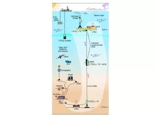
Riser cable will attach to float with electrical/optical(?)/mechanical swivel • Riser cable used fiber optic data telemetry – can pass optical data through swivel or convert to electrical in cable termination • Distance between Float & Crawler CTD sensors (conductivity, temperature, depth) sensors needs to be minimized • EOM Swivel shown in next slide