Download
1 / 18
270 likes | 641 Views
Charging System Service. Chapter 31. Objectives. Measure and interpret voltage drops on the positive side of the charging circuit Measure and interpret voltage drops on the ground side of the charging circuit Test and repair an alternating current (AC) generator

E N D
Charging System Service Chapter 31
Objectives • Measure and interpret voltage drops on the positive side of the charging circuit • Measure and interpret voltage drops on the ground side of the charging circuit • Test and repair an alternating current (AC) generator • Diagnose voltage regulator problems
Introduction • This chapter discusses testing and repair of common charging system problems • Principles of operation and electrical fundamentals are useful • Diagnosis of failures before replacing parts is important • Most parts stores will not accept returns of electrical items
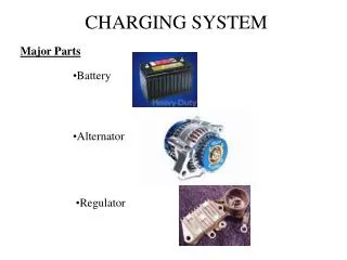
Charging System Service • Common charging system complaints • Dead battery • Battery water low • Indicator light glows • Noises • Perform complete charging system diagnosis • Before replacing parts • Check battery charge • At least 80%: perform 15-second load test • Fails load test: might be sulfated
Testing the Charging System • Perform visual inspection • Corroded or broken wire connections • Indicator lights and gauges functioning correctly • Listen for noises • Loose or damaged alternator drive belt • Loose drive belt causes two problems: • Low charge rate • Rotor shaft overheating can cause drive end bearing failure
Testing the Charging System (cont'd.) • Connect volt-amp tester to battery • Set meter range to highest scales during starting • Adjust to lower ranges as needed • Four charging tests • Charging system output test • Regulator voltage • AC generator full-field test • Charging circuit resistance tests
Charging System Output Test • Procedure • Start the engine • Raise idle speed to 2,000 rpm while lowering battery voltage • Read amount of current put into battery • Maximum output will be more than gauge shows • Move amp probe to B+ wire • More accurate estimate of output • Testing using an amp clamp • Place it around all of wires from battery terminal
Regulator Voltage Check • Regulator must be able to: • Full-field an alternator immediately • Keep the system at predetermined voltage • With engine running, meter should show gradual decrease in charging amperage • Voltage should remain within normal operating limits
Full-Field Test • Low output of AC generator • Could be due to generator or regulator • Full-fielding the alternator eliminates the regulator from the circuit • Energizes the rotor fully • Causes the alternator to produce full output • Full-field test results • If alternator puts out more at same voltage with regulator bypassed: regulator is faulty • When current output remains low: bad alternator or drive belt are probable causes
Full-Field Test (cont’d.) • PCM controlled voltage regulation service • Warning message may or may not be displayed on the instrument panel for the driver • If warning light does not come on when the key is first turned on, look for a problem in that circuit • If the warning message comes on and stays on as the engine runs, check for diagnostic trouble codes
Diode Tests • Leaking diodes decrease alternator output • Diodes: • Rectify AC output to DC • Prevent AC from leaving in the B+ output wire • Are defective if more than 0.5 AC volt in B+ output • With engine off, there should be less than 0.5 milliamp of current flow in B+ output wire
Diode Tests (cont’d.) • Testing diodes with a power probe • Peak-to-peak mode: tester measures differences between positive and negative peak voltage levels • Scope testing • Lab scope can be used to look at AC generator patterns • Diode noises • When the sound is loud enough for a customer complaint, a bad diode is probably the cause
Charging System Voltage Drops • Check voltage drops as preventive maintenance • Combined voltage should be less than 0.5 volts • Positive circuit with 10 amps flowing: no connection should have more than 0.3-volt drop • System with an ammeter: 0.7-volt drop limit • Small amount of voltage drop through the fuse link is normal
AC Generator Service and Repair • Most shops do not repair AC generators • Easy to disassemble • Remove the bolts • Separate the rotor from its housing • Brushes may be serviced without disassembling • Stator is discarded if it has signs of burned or overheated insulation • Test the continuity of the rotor winding for opens, shorts, or grounds • Resistance is checked with ohmmeter
Diode Service • Diodes must be tested under load • Diode tester • Ohmmeter • Good diode • Shows high resistance in one direction • Low resistance in the other • Shorted diode • Low readings in both directions • Open diode • High resistance in both directions
Alternator Reassembly • Reassembling the alternator is not difficult • Brushes inside the frame must be raised against their springs • Slip rings positioned under them • Brushes mount from outside are compressed against springs as holding bracket is installed