DETECTOR BACKGROUNDS AT MUON COLLIDERS
230 likes | 397 Views
Fermilab. Accelerator Physics Center. DETECTOR BACKGROUNDS AT MUON COLLIDERS. Nikolai Mokhov and Sergei Striganov Fermilab. TIPP 2011 Conference Chicago June 9-14, 2011. Outline. Introduction Background Sources MDI and Background Load Modeling Main Characteristics of Backgrounds.

DETECTOR BACKGROUNDS AT MUON COLLIDERS
E N D
Presentation Transcript
Fermilab Accelerator Physics Center DETECTOR BACKGROUNDS AT MUON COLLIDERS Nikolai Mokhov and Sergei Striganov Fermilab TIPP 2011 Conference Chicago June 9-14, 2011
Outline • Introduction • Background Sources • MDI and Background Load Modeling • Main Characteristics of Backgrounds Detector Backgrounds at Muon Colliders - N. Mokhov, S. Striganov
Introduction • Physics goals of a Muon Collider (MC) can only be reached with appropriate design of the ring, interaction region (IR), high-field superconducting magnets, machine-detector interface (MDI) and detector. All - under demanding requirements, arising from the short muon lifetime, relatively large values of the transverse emittance and momentum spread, unprecedented dynamic heat loads (0.5-1 kW/m) and background particle rates in collider detector. Detector Backgrounds at Muon Colliders - N. Mokhov, S. Striganov
Muon Collider Parameters Detector Backgrounds at Muon Colliders - N. Mokhov, S. Striganov
IR & Chromatic Correction Section 8-T dipoles in IR to generate large D at sextupoles to compensate chromaticity and sweep decay products; momentum acceptance 1.2%; dynamic aperture sufficient for transverse emittance of 50 mm; under engineering constraints. Iterative studies on lattice and MDI with magnet experts: High-gradient (field) large-aperture short Nb3Sn quads and dipoles. Detector Backgrounds at Muon Colliders - N. Mokhov, S. Striganov
Sources of Background and Dynamic Heat Load • IP m+m- collisions: Production x-section 1.34 pb at √S = 1.5 TeV (negligible compared to #3). • IP incoherent e+e- pair production: x-section 10 mb which gives rise to background of 3×10⁴ electron pairs per bunch crossing (manageable with nozzle & detector B) • Muon beam decays:Unavoidable bilateral detector irradiation by particle fluxes from beamline components and accelerator tunnel – major source at MC: For 0.75-TeV muon beam of 2x10¹², 4.28x10⁵dec/m per bunch crossing, or 1.28x10¹⁰dec/m/s for 2 beams; 0.5 kW/m. • Beam halo:Beam loss at limiting apertures; severe, can be taken care of by an appropriate collimation system far upstream of IP. Detector Backgrounds at Muon Colliders - N. Mokhov, S. Striganov
MARS15 Modeling • Detailed magnet geometry, materials, magnetic fields maps, tunnel, soil outside and a simplified experimental hall plugged with a concrete wall. • Detector model with Bz = 3.5 T and tungsten nozzle in a BCH2 shell, starting at ±6 cm from IP with R = 1 cm at this z. • 750-GeV bunches of 2×10¹²m- and m+ approaching IP are forced to decay at |S| < Smax, where Smax up to 250 m at 4.28×10⁵ / m rate, 1000 turns. • Cutoff energies optimized for materials & particle types, varying from 2 GeV at ≥100 m to 0.025 eV (n) and 0.2 MeV (others) in the detector. Detector Backgrounds at Muon Colliders - N. Mokhov, S. Striganov
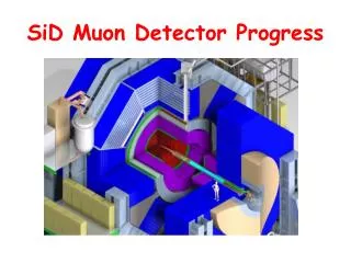
Machine-Detector Interface Q = 10o 6 < z < 600 cm x:z = 1:17 Q = 5o Q1 Sophisticated shielding: W, iron, concrete & BCH2 W BCH2 Detector Backgrounds at Muon Colliders - N. Mokhov, S. Striganov
Background Suppression m Dipoles close to the IP and tungsten masks in each interconnect region help reduce background particle fluxes in the detector by a substantial factor. The tungsten nozzles, assisted by the detector solenoid field, trap most of the decay electrons created close to the IP as well as most of incoherent e+e- pairs generated in the IP. With additional MDI shielding, total reduction of background loads by more than three orders of magnitude is obtained. Detector Backgrounds at Muon Colliders - N. Mokhov, S. Striganov
Load to Detector: Two Nozzles Number of particles per bunch crossing entering detector, starting from MARS source term for Smax=75m 0.6-deg 10-deg No time cut applied, can help substantially All results below are presented for 10-deg nozzle X:Z=1:20 Detector Backgrounds at Muon Colliders - N. Mokhov, S. Striganov
Where is Background Produced?Number of Particles Entering Detector Detector Backgrounds at Muon Colliders - N. Mokhov, S. Striganov
Where is Background Produced?Energy Flow Entering Detector Detector Backgrounds at Muon Colliders - N. Mokhov, S. Striganov
Energy Spectra Entering Detector Detector Backgrounds at Muon Colliders - N. Mokhov, S. Striganov
Time Distribution wrt Bunch crossing at Detector Entrance Detector Backgrounds at Muon Colliders - N. Mokhov, S. Striganov
Spatial Distribution at Detector Entrance Most of particles come to detector through nozzle surface; for muons this fraction is 30% Background (except muons) on nozzle surface weakly depends on azimuthal angle m+ beam Detector Backgrounds at Muon Colliders - N. Mokhov, S. Striganov
Muon Lateral Distribution at Detector Entrance Positive muons deflected by beam-line magnetic field to negative direction Negative muons deflected by beam-line magnetic field to positive direction Detector Backgrounds at Muon Colliders - N. Mokhov, S. Striganov
Background Loads in Detector n Maximum neutron fluence and absorbed dose in the innermost layer of the silicon tracker for a one-year operation are at a 10% level of that in the LHC detectors at the luminosity of 1034 cm-2s-1 Detector Backgrounds at Muon Colliders - N. Mokhov, S. Striganov
Summary • A consistent IR lattice, which satisfies all the requirements from the beam dynamics point of view, has been designed for a 1.5-TeV muon collider with luminosity of 1034 cm-2s-1. • Detector background simulations are advancing well, MDI optimization is underway, files are available to the community. • Main features of background loads on the detector have been studied and are well understood. • Detector physics modeling in presence of the machine backgrounds has been started and progressing very well. Detector Backgrounds at Muon Colliders - N. Mokhov, S. Striganov
Detector Backgrounds at Muon Colliders - N. Mokhov, S. Striganov
Energy spectra in tracker (+-46x46x5cm) with and without tungsten shielding
Nozzle geometry in MARS Standard 10 degree nozzle New nozzle
Comparison new and old shielding Tungsten radiation length – 0.35 cm Tungsten nuclear interaction length – 10 cm. 10 cm tungsten -29 gamma/electron interactions. 10 cm tungsten – 1 proton/neutron interaction. Ratio new/old shielding =============================== number energy Gamma 26 28 Positron 14 8 Electron 26 15 Muon 38 3.5 Neutron 3.2 2.2 Ch hadron 2.5 2.8