Download
1 / 35
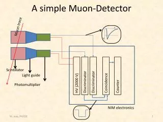
350 likes | 478 Views
Detector Backgrounds in a Muon Collider. Steve Kahn Muons Inc. LEMC Workshop. Introduction.

E N D
Detector Backgrounds in a Muon Collider Steve Kahn Muons Inc. LEMC Workshop S. Kahn -- Muon Collider Detector Backgrounds
Introduction • This talk is a review of previous presentations on muon collider detector backgrounds. Nothing presented here is new. A large fraction of the the detector background studies was performed by Iuliu Stumer. • I will try to convince you that you can do physics at a Muon Collider. • The backgrounds encountered are certainly worse than an ee– collider, but they are no worse and probably better than that expected at the LHC and the LHC will produce physics in that environment! • References: • Snowmas 1996 Feasibility Study • Status Report published in Phys. Rev. AB(1999) • Highest Energy Muon Collider Workshop (Montauk, 1999) • Rosario Muon Collider Workshop (May 1997) • UCLA Workshop (July 1997) • Collider Conference, San Francisco (Dec 1997) S. Kahn -- Muon Collider Detector Backgrounds
Parameters Used For Various Muon Collider Scenarios S. Kahn -- Muon Collider Detector Backgrounds
Background Sources • Muon Decay Background • Electron Showers from high energy electrons. • Lepto-production of hadrons not included in studies. • Not important for 22 TeV or smaller colliders. • Bremsstrahlung Radiation for decay electrons in magnetic fields. • Photonuclear Interactions • Source of hadrons background. • Bethe-Heitler muon production. • Beam Halo • Beam Scraping at 180° from IP to reduce halo. Could it cause some? • Collider sources such as magnet misalignments. • Beam-Beam Interactions. • Believed to be small. S. Kahn -- Muon Collider Detector Backgrounds
Muon Decay Backgrounds • Muon decay backgrounds are expected to be high (see table) • The effort to minimize the backgrounds will have strong influence on • Design of the Detector • Design of the Final Focus for the IR • The IR design itself • If the per bunch can be reduced as we believe can be done for the LEMC, the detector backgrounds will also be reduced. • An order of magnitude reduction is a blessing. • Most of the numbers presented in this talk will refer to the earlier designs with larger numbers of muons per bunch. The results should be scaleable. S. Kahn -- Muon Collider Detector Backgrounds
Muon Decay Background • Upper figure shows electron energy spectrum from decay of 2 TeV muons. • 2×10¹² Muons/bunch in each beam • 2.6×10⁵ decays/meter • Mean Decay Electron energy = 700 GeV • Lower figure shows trajectories of decay electrons. • Electron decay angles are of the order of ~10 microradians. • In the final focus section, the decay electrons tend to stay in the beam pipe until they see the final focus quad fields. S. Kahn -- Muon Collider Detector Backgrounds
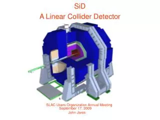
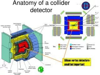
Strawman Detector Concept for a Muon Collider S. Kahn -- Muon Collider Detector Backgrounds
The Intersection Region as Modeled in Geant for 2×2 TeV Muon Collider 130 m Region from IP Final Focus Quadrupoles 5 m High Field Dipole Magnets to Sweep Upstream Decay Electrons 20 m S. Kahn -- Muon Collider Detector Backgrounds
IP Region for 2×2 TeV(Similar Diagrams for other Energies) Tracker Region Vertex Detector Borated Polyethelene for neutron capture 20º Tungsten Cone For electromagnetic shielding Last final focus quadrupole The figure represents 10 meters around the IP S. Kahn -- Muon Collider Detector Backgrounds
Interior Design of the Tungsten Shielding • The tungsten shielding is designed so that the detector is not connected by a straight line with any surface surface hit by a decay electron in forward or backward direction. 50×50 GeV case 250×250 GeV case Borated Polyethelene W Cu S. Kahn -- Muon Collider Detector Backgrounds
Summarizing Shielding Configuration to Reduce Backgrounds • 20 degree conical tungsten shield in forward/backward direction. • Expanding inner cone from minimum aperture point is set at 4 beam size. • Inverse cone between IP and minimum aperture point is set to 4 beam divergence. • Designed so detector does not see surfaces struck by incident electrons. • Inner surface of each shield shaped into collimating steps and slopes to maximize absorption of electron showers. • Reduces low energy electrons in beam pipe. • High field sweeping dipole magnets placed upstream of first quadrupole. These dipoles have collimators inside to sweep decay electrons in advance of final collimation. S. Kahn -- Muon Collider Detector Backgrounds
Electrons in the Intersection Region • Top figure shows the expanded view of the region near the IP. • The lines represent electrons from a random sample of muon decays. • Electrons are removed by interior collimation surfaces. • The bottom figure shows a detailed view of the IR. • Electrons from a random set of muon decays. • Electrons do not make it into the detector region. S. Kahn -- Muon Collider Detector Backgrounds
IP Configuration Parameters S. Kahn -- Muon Collider Detector Backgrounds
Synchrotron Radiation • The decay electrons radiate synchrotron photons as they propagate through the fields in the final focus region, losing on the average about 20% of their energy. • Each electron radiates on the average 300 synchrotron photons. • The synchrotron photons carry small energy and do not point to small opening at the intersection region. • The resulting background, however, in the detector region is small compared to the other backgrounds because of the design of the shielding as previously described. <E>=500 MeV Log( ) S. Kahn -- Muon Collider Detector Backgrounds
Incoherent Pair Production • Incoherent pair production from ee can be significant for high energy muon colliders. • Estimated cross section of 10 mb giving 3×10⁴ electron pairs per bunch crossing. • The electron pairs have small transverse momentum, but the on-coming beam can deflect them towards the detector. • Figures show examples of electron pairs tracked near the detector in the presence of the detector solenoid field. • With a 2 Tesla field, only 10% of electrons make it 10 cm into the detector. With 4 Tesla field no electrons reach 10 cm. S. Kahn -- Muon Collider Detector Backgrounds
Photonuclear Interactions • This is the primary source of hadron background. • The probability for photo production is small relative to other processes. • Large numbers of photons released per crossing make this an important background. • Different mechanisms in different energy bands: • Giant Dipole Resonance Region • 5<E<30 MeV • Produce ~1 neutron • Quasi-Deuteron Region • 30<E< 150 MeV • Produce ~1 neutron • Baryon Resonance Region • 150 MeV<E<2 GeV • Produce and nucleons • Vector Dominance Region • E>2 GeV • Produce 0 that decay to . • GEANT 3.2.1 had to be modified to include photonuclear production. (I think that GEANT 4 includes these.) S. Kahn -- Muon Collider Detector Backgrounds
Gamma Nuclear Interaction Models S. Kahn -- Muon Collider Detector Backgrounds
Neutron Background Generated Neutron Spectrum Neutron Spectrum Seen in Detector Log( ) Log( ) ) S. Kahn -- Muon Collider Detector Backgrounds
Time Distribution of Neutron Background • The top distribution shows the time distribution of the neutron background generated. • The lower distribution shows the time distribution of the neutron background that is seen in the tracker. • The neutron flux has fallen by two orders of magnitude before the next bunch crossing (10 s later). S. Kahn -- Muon Collider Detector Backgrounds
Pion Background in the Detector S. Kahn -- Muon Collider Detector Backgrounds
Photon and Neutron Fluxes at Radial Planes S. Kahn -- Muon Collider Detector Backgrounds
Silicon Pad Occupancy as a Function of Radial Position S. Kahn -- Muon Collider Detector Backgrounds
Bethe-Heitler Muons • Electrons interacting with the beam pipe wall or tungsten shielding can produce muon pairs. We call these muon pairs Bethe-Heitler Muons. • These ’s can penetrate the shielding to reach the detector. • Some Bethe-Heitler ’s will cross the calorimeter and produce catastrophic bremsstrahlung losses that could put spikes in the energy distribution. • Time-of-Flight information: • Fast timing can remove B-H ’s in the central calorimeter. • Significant number of B-H ’s in for forward calorimeter are likely to be in time with the signal. • Fine Segmentation in both longitudinal and transverse directions will be necessary to distinguish B-H background from signal. S. Kahn -- Muon Collider Detector Backgrounds
Bethe-Heitler Muon Spectrum S. Kahn -- Muon Collider Detector Backgrounds
Bethe-Heitler Muon Trajectories for the 2×2 TeV Collider S. Kahn -- Muon Collider Detector Backgrounds
Effect of Timing on Bethe-Heitler Muons S. Kahn -- Muon Collider Detector Backgrounds
Conclusions • A carefully optimized design of the detector and the final focus system of the collider ring can significantly reduce the detector backgrounds. • The reduction of detector backgrounds will be an important consideration in the design of the collider ring. • With the proper design the background levels are likely to be les than those expected at the LHC. S. Kahn -- Muon Collider Detector Backgrounds