Image Formation Fundamentals
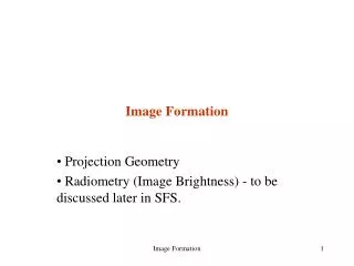
This overview explores the fundamental concepts of image formation and representation in computer vision. It covers image digitization, encompassing sampling and quantization processes, and illustrates how images are represented as rectangular arrays of integers corresponding to brightness levels. The principles of image formation, including geometry and the physics of light, are discussed, along with practical examples of the effects of sampling factors and quantization levels. Additionally, we delve into camera models, including pinhole cameras and lens characteristics, to understand how images are captured and portrayed.


Image Formation Fundamentals
E N D
Presentation Transcript
Image Formation Fundamentals Basic Concepts (Continued…)
How are images represented in the computer? courstey UNR computer vision course
Image digitization • Sampling means measuring the value of an image at a finite number of points. • Quantization is the representation of the measured value at the sampled point by an integer. courstey UNR computer vision course
Image digitization (cont’d) courstey UNR computer vision course
Image quantization (Example) 256 gray levels (8bits/pixel) 32 gray levels (5 bits/pixel) 16 gray levels (4 bits/pixel) 8 gray levels (3 bits/pixel) 4 gray levels (2 bits/pixel) 2 gray levels (1 bit/pixel) courstey UNR computer vision course
Image sampling (example) • original image sampled by a factor of 2 • sampled by a factor of 4 sampled by a factor of 8 courstey UNR computer vision course
Digital image • An image is represented by a rectangular array of integers. • An integer represents the brightness or darkness of the image at that point. • N: # of rows, M: # of columns, Q: # of gray levels • N = , M = , Q = (q is the # of bits/pixel) • Storage requirements: NxMxQ (e.g., N=M=1024, q=8, 1MB) courstey UNR computer vision course
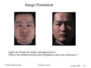
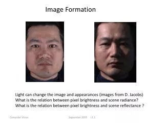
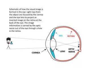
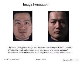
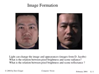
Image formation • There are two parts to the image formation process: • The geometry of image formation, which determines where in the image plane the projection of a point in the scene will be located. • The physics of light, which determines the brightness of a point in the image plane as a function of illumination and surface properties. courstey UNR computer vision course
A Simple model of image formation • The scene is illuminated by a single source. • The scene reflects radiation towards the camera. • The camera senses it via chemicals on film. courstey UNR computer vision course
Abstract camera model - box with a small hole in it Pinhole cameras work in practice Pinhole cameras courstey Dr. G. D. Hager
Real Pinhole Cameras Pinhole too big - many directions are averaged, blurring the image Pinhole too small- diffraction effects blur the image Generally, pinhole cameras are dark, because a very small set of rays from a particular point hits the screen. courstey Dr. G. D. Hager
The reason for lenses Lenses gather andfocus light, allowingfor brighter images. courstey Dr. G. D. Hager
The thin lens • Thin Lens Properties: • A ray entering parallel to optical axisgoes through the focal point. • A ray emerging from focal point is parallel to optical axis • A ray through the optical center is unaltered courstey Dr. G. D. Hager
The thin lens Note that, if the image plane is very small and/or z >> z’, then z’ is approximately equal to f courstey Dr. G. D. Hager
Lens Realities Real lenses have a finite depth of field, and usuallysuffer from a variety of defects Spherical Aberration vignetting courstey Dr. G. D. Hager
Equating z’ and f We have, by similar triangles, that (x, y, z) -> (-f x/z, -f y/z, -f) Ignore the third coordinate, and flip the image around to get: The equation of projection courstey Dr. G. D. Hager
Distant objects are smaller courstey Dr. G. D. Hager
Parallel lines meet common to draw film plane in front of the focal point A Good Exercise: Show this is the case! courstey Dr. G. D. Hager
Orthographic projection Suppose I let f go to infinity; then courstey Dr. G. D. Hager
The model for orthographic projection courstey Dr. G. D. Hager
Issue perspective effects, but not over the scale of individual objects collect points into a group at about the same depth, then divide each point by the depth of its group Adv: easy Disadv: wrong Weak perspective courstey Dr. G. D. Hager
The model for weak perspective projection courstey Dr. G. D. Hager
Model for perspective projection courstey Dr. G. D. Hager
Intrinsic Parameters Intrinsic Parameters describe the conversion fromunit focal length metric to pixel coordinates (and the reverse) It is common to combine scale and focal length together as the are both scaling factors; note projection is unitless in this case! courstey Dr. G. D. Hager
pixel coordinate system image coordinate system Scaling factor = depth of the point X world coordinate system (R,T) camera coordinate system Image formation - Recap x1 If we consider unit focal length Taken from MASKS (invitation to 3D vision)
Summary: points expressed in external frame points are converted to canonical camera coordinates points are projected points are converted to pixel units Camera parameters point in pixel coords. point in metric image coords. point in cam. coords. point in world coords. courstey Dr. G. D. Hager
Camera Calibration The problem: Compute the camera intrinsic and extrinsic parameters using only observed camera data.
Calibration with a Rig Use the fact that both 3-D and 2-D coordinates of feature points on a pre-fabricated object (e.g., a cube) are known.
Calibration with Multiple Plane Images Actually used in practice these days