Download
1 / 25
250 likes | 1.57k Views
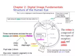
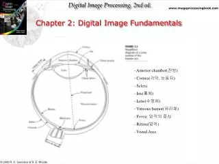
Image Fundamentals. How are images represented in the computer?. Color images. Image formation. There are two parts to the image formation process:

E N D
Image formation • There are two parts to the image formation process: • The geometry of image formation, which determines where in the image plane the projection of a point in the scene will be located. • The physics of light, which determines the brightness of a point in the image plane as a function of illumination and surface properties.
A Simple model of image formation • The scene is illuminated by a single source. • The scene reflects radiation towards the camera. • The camera senses it via chemicals on film.
Pinhole camera • This is the simplest device to form an image of a 3D scene on a 2D surface. • Straight rays of light pass through a “pinhole” and form an inverted image of the object on the image plane.
Camera optics • In practice, the aperture must be larger to admit more light. • Lenses are placed to in the aperture to focus the bundle of rays from each scene point onto the corresponding point in the image plane
Image formation (cont’d) • Optical parameters of the lens • lens type • focal length • field of view • Photometric parameters • type, intensity, and direction of illumination • reflectance properties of the viewed surfaces • Geometric parameters • type of projections • position and orientation of camera in space • perspective distortions introduced by the imaging process
What is light? • The visible portion of the electromagnetic (EM) spectrum. • It occurs between wavelengths of approximately 400 and 700 nanometers.
Short wavelengths • Different wavelengths of radiation have different properties. • The x-ray region of the spectrum, it carries sufficient energy to penetrate a significant volume or material.
Long wavelengths • Copious quantities of infrared (IR) radiation are emitted from warm objects (e.g., locate people in total darkness).
Long wavelengths (cont’d) • “Synthetic aperture radar” (SAR) imaging techniques use an artificially generated source of microwaves to probe a scene. • SAR is unaffected by weather conditions and clouds (e.g., has provided us images of the surface of Venus).
Range images • An array of distances to the objects in the scene. • They can be produced by sonar or by using laser rangefinders.
Sonic images • Produced by the reflection of sound waves off an object. • High sound frequencies are used to improve resolution.
CCD (Charged-Coupled Device) cameras • Tiny solid state cells convert light energy into electrical charge. • The image plane acts as a digital memory that can be read row by row by a computer.
Frame grabber • Usually, a CCD camera plugs into a computer board (frame grabber). • The frame grabber digitizes the signal and stores it in its memory (frame buffer).
Image digitization • Sampling means measuring the value of an image at a finite number of points. • Quantization is the representation of the measured value at the sampled point by an integer.
Image quantization(example) • 256 gray levels (8bits/pixel) 32 gray levels (5 bits/pixel) 16 gray levels (4 bits/pixel) • 8 gray levels (3 bits/pixel) 4 gray levels (2 bits/pixel) 2 gray levels (1 bit/pixel)
Image sampling (example) • original image sampled by a factor of 2 • sampled by a factor of 4 sampled by a factor of 8
Digital image • An image is represented by a rectangular array of integers. • An integer represents the brightness or darkness of the image at that point. • N: # of rows, M: # of columns, Q: # of gray levels • N = , M = , Q = (q is the # of bits/pixel) • Storage requirements: NxMxQ (e.g., N=M=1024, q=8, 1MB)
Image file formats • Many image formats adhere to the simple model shown below (line by line, no breaks between lines). • The header contains at least the width and height of the image. • Most headers begin with a signature or “magic number” - a short sequence of bytes for identifying the file format.
Common image file formats • GIF (Graphic Interchange Format) - • PNG (Portable Network Graphics) • JPEG (Joint Photographic Experts Group) • TIFF (Tagged Image File Format) • PGM (Portable Gray Map) • FITS (Flexible Image Transport System)