Image formation
Image formation. ECE 847: Digital Image Processing. Stan Birchfield Clemson University. Cameras. First photograph due to Niepce Basic abstraction is the pinhole camera lenses required to ensure image is not too dark various other abstractions can be applied.


Image formation
E N D
Presentation Transcript
Image formation ECE 847:Digital Image Processing Stan Birchfield Clemson University
Cameras • First photograph due to Niepce • Basic abstraction is the pinhole camera • lenses required to ensure image is not too dark • various other abstractions can be applied F. Dellaert, http://www.cc.gatech.edu/~dellaert/vision/html/materials.html
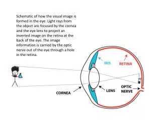
Image formation overview Image formation involves • geometry – path traveled by light • radiometry – optical energy flow • photometry – effectiveness of light to produce “brightness” sensation in human visual system • colorimetry – physical specifications of light stimuli that produce given color sensation • sensors – converting photons to digital form
Pinhole camera D. Forsyth, http://luthuli.cs.uiuc.edu/~daf/book/bookpages/slides.html
Parallel lines meet: vanishing point • each set of parallel lines (=direction) meets at a different point • The vanishing point for this direction • Sets of parallel lines on the same plane lead to collinear vanishing points. • The line is called the horizon for that plane
Properties of projection: Points go to points Lines go to lines Planes go to whole image Polygons go to polygons Degenerate cases line through focal point to point plane through focal point to line k P p i C Q f q O j Perspective projection F. Dellaert, http://www.cc.gatech.edu/~dellaert/vision/html/materials.html
Perspective projection (cont.) F. Dellaert, http://www.cc.gatech.edu/~dellaert/vision/html/materials.html
perspective effects, but not over the scale of individual objects collect points into a group at about the same depth, then divide each point by the depth of its group Weak perspective projection D. Forsyth, http://luthuli.cs.uiuc.edu/~daf/book/bookpages/slides.html
Weak perspective (cont.) F. Dellaert, http://www.cc.gatech.edu/~dellaert/vision/html/materials.html
Orthographic projection Let Z0=1: F. Dellaert, http://www.cc.gatech.edu/~dellaert/vision/html/materials.html
Pinhole size Pinhole too big - many directions are averaged, blurring the image Pinhole too small- diffraction effects blur the image Generally, pinhole cameras are dark, because a very small set of rays from a particular point hits the screen. D. Forsyth, http://luthuli.cs.uiuc.edu/~daf/book/bookpages/slides.html
The reason for lenses D. Forsyth, http://luthuli.cs.uiuc.edu/~daf/book/bookpages/slides.html
focal points The thin lens D. Forsyth, http://luthuli.cs.uiuc.edu/~daf/book/bookpages/slides.html
Focusing http://www.theimagingsource.com
Thick lens • thick lens has 6 cardinal points: • two focal points (F1 and F2) • two principal points (H1 and H2) • two nodal points (N1 and N2) • complex lens is formed by combining individual concave and convex lenses http://physics.tamuk.edu/~suson/html/4323/thick.html D. Forsyth, http://luthuli.cs.uiuc.edu/~daf/book/bookpages/slides.html
Complex lens All but the simplest cameras contain lenses which are actually composed of several lens elements http://www.cambridgeincolour.com/tutorials/camera-lenses.htm
Choosing a lens • How to select focal length: • x=fX/Z • f=xZ/X • Lens format should be >= CCD format to avoid optical flaws at the rim of the lens http://www.theimagingsource.com/en/resources/whitepapers/download/choosinglenswp.en.pdf
Lenses – Practical issues • standardized lens mount has two varieties: • C mount • CS mount • CS mount lenses cannot be used with C mount cameras http://www.theimagingsource.com/en/resources/whitepapers/download/choosinglenswp.en.pdf
Spherical aberration perfect lens actual lens On a real lens, even parallel rays are not focused perfectly http://en.wikipedia.org/wiki/Spherical_aberration
Chromatic aberration On a real lens, different wavelengths are not focused the same http://en.wikipedia.org/wiki/Chromatic_aberration
Radial distortion straight lines are curved: uncorrected corrected
Radial distortion (cont.) Two types: barrel distortion(more common) pincushion distortion barrel pincushion http://en.wikipedia.org/wiki/Image_distortion http://foto.hut.fi/opetus/260/luennot/11/atkinson_6-11_radial_distortion_zoom_lenses.jpg
Vignetting vignetting – reduction of brightness at periphery of image D. Forsyth, http://luthuli.cs.uiuc.edu/~daf/book/bookpages/slides.html
Normalized Image coordinates 1 O u=X/Z = dimensionless ! P F. Dellaert, http://www.cc.gatech.edu/~dellaert/vision/html/materials.html
Pixel units Pixels are on a grid of a certain dimension f O u=k f X/Z = in pixels ! [f] = m (in meters) [k] = pixels/m P F. Dellaert, http://www.cc.gatech.edu/~dellaert/vision/html/materials.html
Pixel coordinates We put the pixel coordinate origin on topleft f O u=u0 + k f X/Z P F. Dellaert, http://www.cc.gatech.edu/~dellaert/vision/html/materials.html
Pixel coordinates in 2D 640 (0.5,0.5) i (u0,v0) 480 (640.5,480.5) j F. Dellaert, http://www.cc.gatech.edu/~dellaert/vision/html/materials.html
skew Summary: Intrinsic Calibration 5 Degrees of Freedom ! F. Dellaert, http://www.cc.gatech.edu/~dellaert/vision/html/materials.html
Camera Pose In order to apply the camera model, objects in the scene must be expressed in camera coordinates. Camera Coordinates World Coordinates Calibration target looks tilted from camera viewpoint. This can be explained as a difference in coordinate systems. F. Dellaert, http://www.cc.gatech.edu/~dellaert/vision/html/materials.html
Rigid Body Transformations • Need a way to specify the six degrees-of-freedom of a rigid body. • Why are there 6 DOF? A rigid body is a collection of points whose positions relative to each other can’t change Fix one point, three DOF Fix second point, two more DOF (must maintain distance constraint) Third point adds one more DOF, for rotation around line F. Dellaert, http://www.cc.gatech.edu/~dellaert/vision/html/materials.html
Notations • Superscript references coordinate frame • AP is coordinates of P in frame A • BP is coordinates of P in frame B • Example: F. Dellaert, http://www.cc.gatech.edu/~dellaert/vision/html/materials.html
Translation F. Dellaert, http://www.cc.gatech.edu/~dellaert/vision/html/materials.html
Translation • Using homogeneous coordinates, translation can be expressed as a matrix multiplication. • Translation is commutative F. Dellaert, http://www.cc.gatech.edu/~dellaert/vision/html/materials.html
Rotation means describing frame A in The coordinate system of frame B F. Dellaert, http://www.cc.gatech.edu/~dellaert/vision/html/materials.html
Rotation Orthogonal matrix! F. Dellaert, http://www.cc.gatech.edu/~dellaert/vision/html/materials.html
Example: Rotation about z axis What is the rotation matrix? F. Dellaert, http://www.cc.gatech.edu/~dellaert/vision/html/materials.html
Rotation in homogeneous coordinates • Using homogeneous coordinates, rotation can be expressed as a matrix multiplication. • Rotation is not communicative F. Dellaert, http://www.cc.gatech.edu/~dellaert/vision/html/materials.html
Rigid transformations F. Dellaert, http://www.cc.gatech.edu/~dellaert/vision/html/materials.html
Rigid transformations (con’t) • Unified treatment using homogeneous coordinates. F. Dellaert, http://www.cc.gatech.edu/~dellaert/vision/html/materials.html
Projective Camera Matrix 5+6 DOF = 11 ! F. Dellaert, http://www.cc.gatech.edu/~dellaert/vision/html/materials.html
Projective Camera Matrix 5+6 DOF = 11 ! F. Dellaert, http://www.cc.gatech.edu/~dellaert/vision/html/materials.html
Columns & Rows of M m2P=0 O F. Dellaert, http://www.cc.gatech.edu/~dellaert/vision/html/materials.html
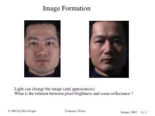
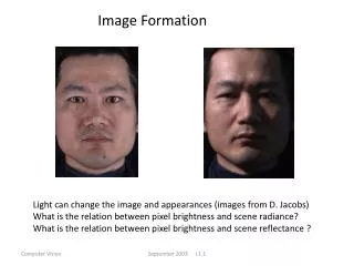
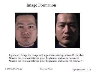
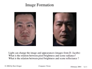
Effect of Illumination Light source strength and direction has a dramatic impact on distribution of brightness in the image (e.g. shadows, highlights, etc.) (Subject 8 from the Yale face database due to P. Belhumeur et. al.) F. Dellaert, http://www.cc.gatech.edu/~dellaert/vision/html/materials.html
Image formation • Light source emits photons • Absorbed, transmitted, scattered • fluorescence source Camera F. Dellaert, http://www.cc.gatech.edu/~dellaert/vision/html/materials.html
Surfaces receives and emits • Incident light from lightfield • Act as a light source • How much light ? F. Dellaert, http://www.cc.gatech.edu/~dellaert/vision/html/materials.html
Irradiance • Irradiance – amount of light falling on a surface patch • symbol=E, units = W/m2 dA F. Dellaert, http://www.cc.gatech.edu/~dellaert/vision/html/materials.html
Radiosity • power leaving a point per area • symbol=B, units = W/m2 dA F. Dellaert, http://www.cc.gatech.edu/~dellaert/vision/html/materials.html
Light = Directional • Light emitted varies w. direction F. Dellaert, http://www.cc.gatech.edu/~dellaert/vision/html/materials.html
Steradians (Solid Angle) • 3D analogue of 2D angle A R F. Dellaert, http://www.cc.gatech.edu/~dellaert/vision/html/materials.html